Chapter 1 | Chapter 2 | Chapter 3 | Chapter 4 | Chapter 5
Chapter 6 | Chapter 7 | Chapter 8 | Chapter 9
Appendix A | Appendix B

PREVIOUS INDEX NEXT

Chapter 4
High Resolution Mirror Assembly (HRMA)

4.1  Introduction

The Chandra X-ray telescope consists of 4 pairs of concentric thin-walled, grazing-incidence Wolter Type-I mirrors (X-ray optics are reviewed by Aschenbach 1985) called the High Resolution Mirror Assembly (HRMA). The front mirror of each pair is a paraboloid (Pn) and the back a hyperboloid (Hn). The eight mirrors were fabricated from Zerodur glass, polished, and coated with iridium on a binding layer of chromium.

4.1.1  Description and Physical Configuration

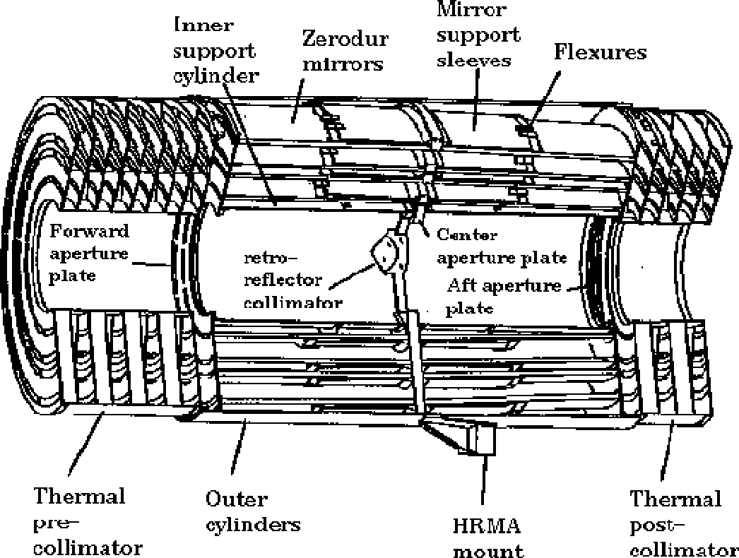
The HRMA, shown schematically in Figure 4.1, contains the nested mirrors, center, forward and aft aperture plates, baffles, inner and outer cylinders, mounts, pre- and post-collimators, fiducial light transfer components, mirror support sleeves, forward and aft contamination covers, flux contamination monitors, and thermal control hardware. The outer mirror pair is number 1, and, progressing inwards, 3, 4, and 6. The original design had six mirror pairs; numbers 2 and 5 were eliminated. The pair diameters range from about 0.65 to 1.23 meters. The distance from the center of the Central Aperture Plate (CAP) separating the paraboloid and hyperboloid mirrors to the HRMA focus is 10.0548 meters, with each mirror pair varying slightly about this value. Note that this distance is close to, but not exactly, the focal length. An annular on-axis beam enters each mirror pair, is reflected from paraboloids and hyperboloids, and exits to converge to a focus. The angle θ between the direction of the reflected ray and the optical axis lies between two cone angles θc and θd. These and other important HRMA characteristics are listed in Table 4.1.
Figure 4.1: The four nested HRMA mirror pairs and associated structures.
Table 4.1: Chandra HRMA Characteristics

    Optics Wolter Type-I
    Mirror coating Iridium (330 Å, nominal)
    Mirror outer diameters (1, 3, 4, 6)1.23, 0.99, 0.87, 0.65 m
    Mirror lengths (Pn or Hn) 84 cm
    Total length (pre- to post-collimator) 276 cm
    Unobscured clear aperture 1145 cm2
    Mass 1484 kg
    Focal length 10.070 ±0.003 m
    Plate scale 48.82 ±0.02 μm arcsec1
    Exit cone angles from each hyperboloid:
      θc (1, 3, 4, 6)3.42°, 2.75°, 2.42°, 1.80°
      θd (1, 3, 4, 6)3.50°, 2.82°, 2.49°, 1.90°
    f-ratios (1, 3, 4, 6)8.4, 10.4, 11.8, 15.7
    PSF FWHM (with detector) < 0.5 arcsec
   
Effective area:
@ 0.25 keV 800 cm2
@ 5.0 keV 400 cm2
@ 8.0 keV 100 cm2
    Ghost-free field of view 30 arcmin diameter

4.1.2  Sub-Assembly Calibration

Extensive measurements of the mirror shapes and of the surface characteristics were made at Hughes Danbury Optical Systems during fabrication of the mirror segments and during assembly at Eastman Kodak Co. HRMA throughput depends critically on the coating of the individual mirror elements carried out at Optical Coating Laboratory in Santa Rosa, California. Mirror flats were present in the coating chamber and coated with iridium at the same time as the HRMA mirror elements. Reflectivity of X-rays from these witness flats was measured with the X-ray beam from the synchrotron at the Brookhaven National Laboratory (Graessle et al. 1998, 2004).

4.1.3  Operating Environment

Insulation and heaters maintain the HRMA temperature at 70 °F (21 °C) on-orbit to minimize changes from the assembly and alignment environments and to minimize molecular contamination.

4.1.4  Heritage

The Chandra mirrors represent a logical progression from those of the Einstein (Giacconi et al. 1979) and Röntgensatellit (ROSAT; Trümper 1983, Aschenbach 1991) missions. Both of these previous X-ray observatories utilized nested Wolter Type-I optics with about 4 arcsec angular resolution. The Einstein mirror assembly had considerably less geometric area than Chandra, while ROSAT had comparable area (1100 cm2) at low energies ( < 1 keV).
To verify the technology required for the spatial resolution of Chandra, a Validation Engineering Test Article-I (VETA-I ) was constructed and tested in 1991. VETA-I contained the P1H1 proto-flight mirror shells constructed to final tolerances, but uncoated and with ends uncut. The VETA-I tests included the image full width at half-maximum (FWHM), encircled energy, effective area, and ring focus properties (for azimuthal and low spatial-frequency figure). Many of the results of these tests appear in Society of Photo-Optical Instrumentation Engineers (SPIE) Proceedings 1742. A good overview of the VETA tests is given by Zhao et al. (1994).

4.2  Calibration and Performance

4.2.1  Calibration and Model

Before launch, the HRMA underwent extensive ground calibration tests at the X-Ray Calibration Facility (XRCF) at Marshall Space Flight Center (MSFC), Huntsville, AL, from 1996-Sep through 1997-May. The full HRMA XRCF Calibration Report is accessible at https://cxc.harvard.edu/cal/Hrma/XRCFReport.html. During these tests, the mirror assembly was mounted horizontally in a vacuum chamber and irradiated with X-rays from various electron-impact sources located at a distance of 524.7 meters. The data taken at the XRCF include the effective area and image distributions as a function of incident energy and angle. The mirror performance during these tests differs from that expected in space because of gravity distortions and the finite source size and distance; consequently, the calibration data cannot be directly compared to flight observations. The approach taken was to develop a model based upon surface and assembly measurements taken before the X-ray calibration activity. The X-ray calibration data then were used to validate this model and to make minor adjustments in model parameters to achieve satisfactory agreement with the observations. Further minor modifications were made as a result of flight experience. A series of papers in SPIE Proceedings 3113 report the results of the HRMA ground calibration.
The HRMA characteristics illustrated in this chapter were generated by a raytrace program using this model. Note that this chapter typically gives characteristics of the HRMA only; unless otherwise indicated, blurring caused by the detector and the aspect solution is not included. These effects are very important for on-axis sources, and are included in the instrument chapters (Chapters 6 and 7). See also Section 4.4.

4.2.2  HRMA Effective Area

The unobscured geometric aperture of the HRMA is 1145 cm2. The obstruction of the HRMA aperture by supporting struts is less than 10%. Since reflectivity of the mirror optics depends on photon energy as well as grazing angle, the HRMA throughput varies with X-ray energy.
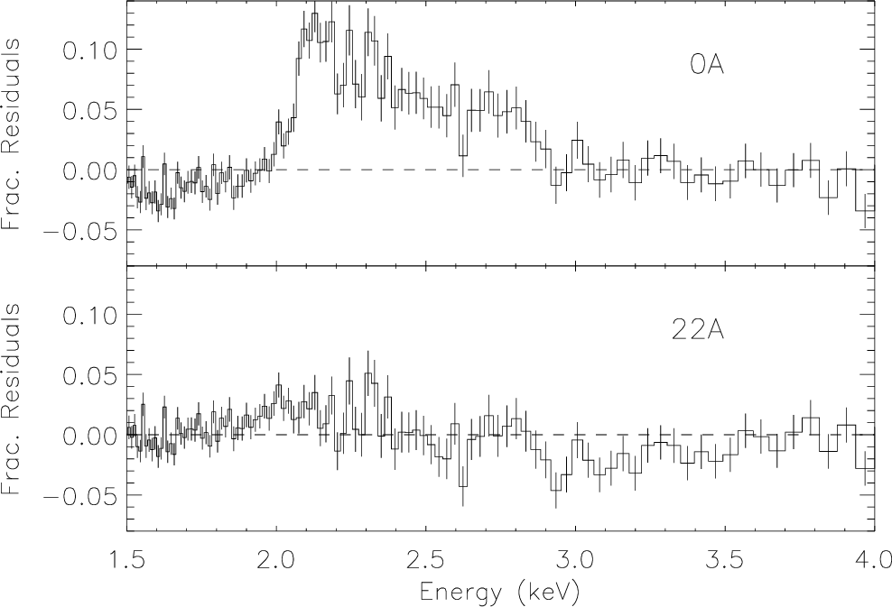
The HRMA effective area is derived from the predictions of the raytrace code discussed above along with empirical corrections based on the XRCF ground-based calibration data. The initial XRCF correction— the correction used to calculate the HRMA effective area prior to Calibration Database (CALDB) 4.1.1—was derived assuming that there was no molecular contamination on the mirrors. Subsequent in-flight gratings observations of blazars showed a discontinuity in the spectrum near the Ir-M edges when reduced with the contaminant free model; this suggests that there may be molecular contamination on the mirrors on-orbit (see Figure 4.2). Using these data and raytrace simulations, it was estimated that a 22 Å layer of hydrocarbon could be present on the mirror optics. An updated HRMA effective area was released in CALDB 3.2.1 on 2005-Dec-15 based on the predictions of the raytrace code with a uniform 22 Å layer of hydrocarbon molecular contamination on all 8 pieces of optics on-orbit.
Subsequently, inconsistencies in the measurements of cluster temperatures derived by two different methods (line and continuum measures) led to a re-analysis of the data taken at the XRCF. This re-analysis provided evidence that molecular contamination was already present on the mirrors at XRCF. Thus, since the initial, ad-hoc, empirical correction of the HRMA model had already corrected for most of the effects of the molecular contamination, the addition of another 22 Å of contamination in the raytrace model post-launch (CALDB 3.2.1) was an over-correction.
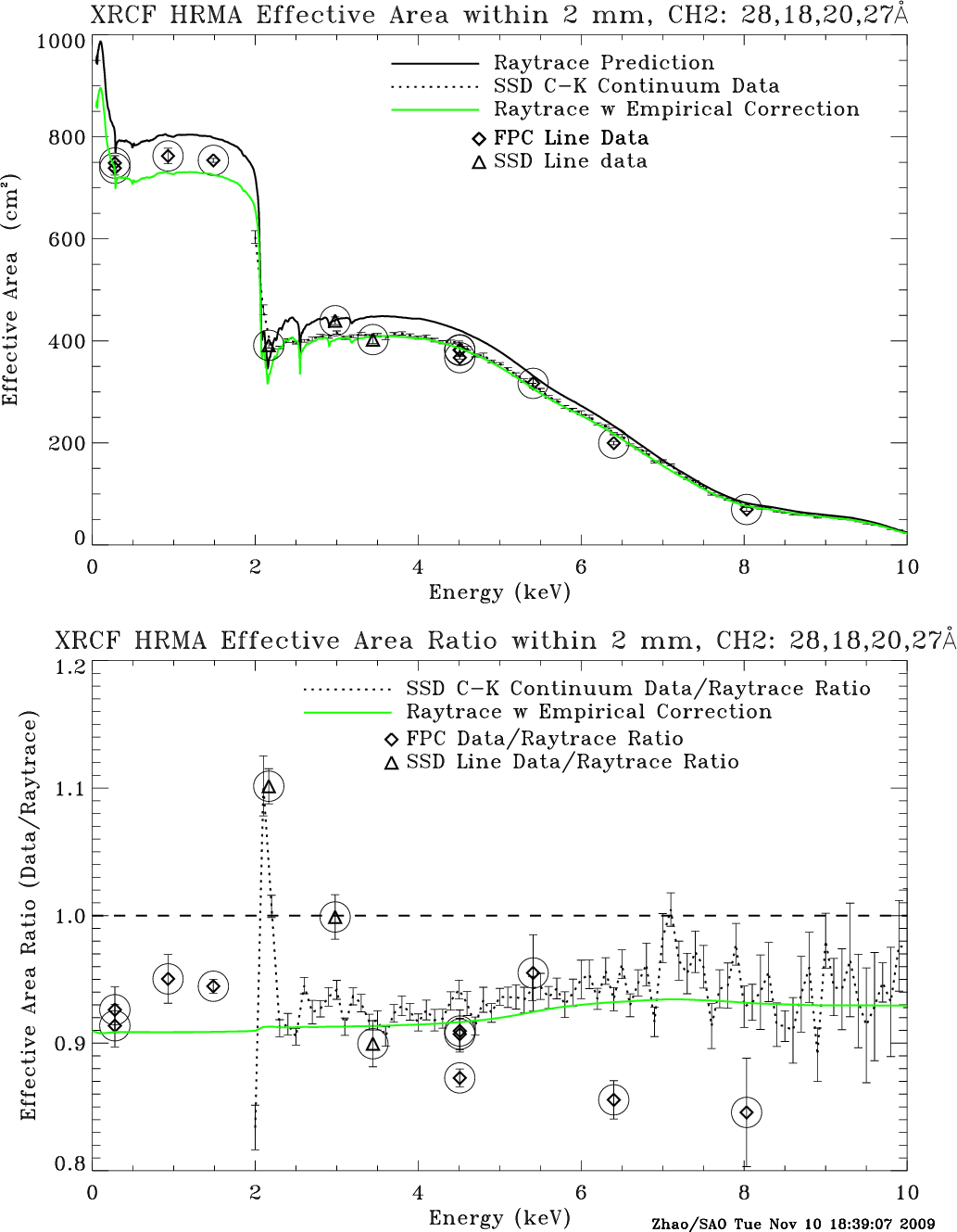
During XRCF testing, a system of shutters was placed behind the HRMA so that the effective area of the 4 shells could be measured independently. These tests were essential since the gratings intercept X-rays from different shells. Two focal-plane instruments were used during XRCF testing: 1) a flow proportional counter (FPC) and 2) a solid-state detector (SSD). Both of these instruments were non-imaging detectors and were used in conjunction with a number of different pin hole apertures. Using the data obtained from each mirror pair, the thicknesses of the contaminant on shells 1, 3, 4 and 6 were determined to be 28, 18, 20 and 27 Å respectively. Thus a new version of the HRMA effective area (CALDB 4.1.1) was released in 2009-Jan, based on the predictions of the raytrace code with the as-measured contamination depths on each shell. In addition, an energy independent correction is applied to the predictions of the raytrace code for each shell to determine the absolute effective area. The correction factor for each shell is calculated by averaging the averaged FPC line data to raytrace ratio and the averaged SSD continuum data to raytrace ratio. Note that, while a gray (i.e. energy-independent) correction is applied to each shell, the overall empirical correction for the full HRMA absolute effective area is not energy-independent, since different shells contribute a different fraction of the total effective area at different energies (see Figure 4.3). This figure reflects an even more refined analysis of the XRCF data than what was used in calculating the HRMA effective area in the CALDB 4.1.1 release. The new analysis results in a slightly lower effective area but is still consistent with the CALDB 4.1.1 data within errors.
Several HRMA effective area models have been generated with different methods for calculating the gray corrections for each shell (e.g., no gray correction or gray corrections with unequal weighting between the FPC and SSD data) to determine the systematic effect of the gray corrections on the gas temperatures derived from ACIS observations of clusters of galaxies. For cool clusters (kT < 4 keV), the derived gas temperatures are essentially independent of the method used to calculate the gray correction. For hotter clusters, the derived temperatures vary by ± 2% depending on the algorithm used.
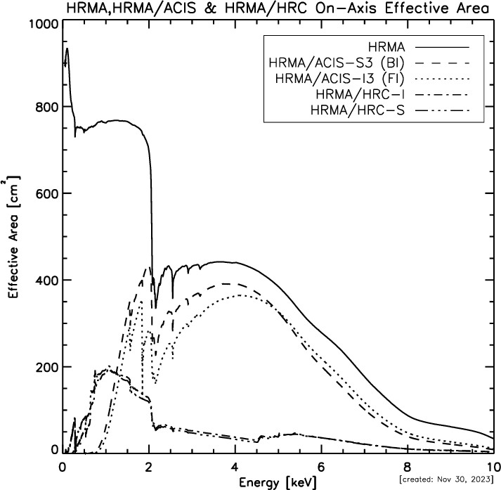
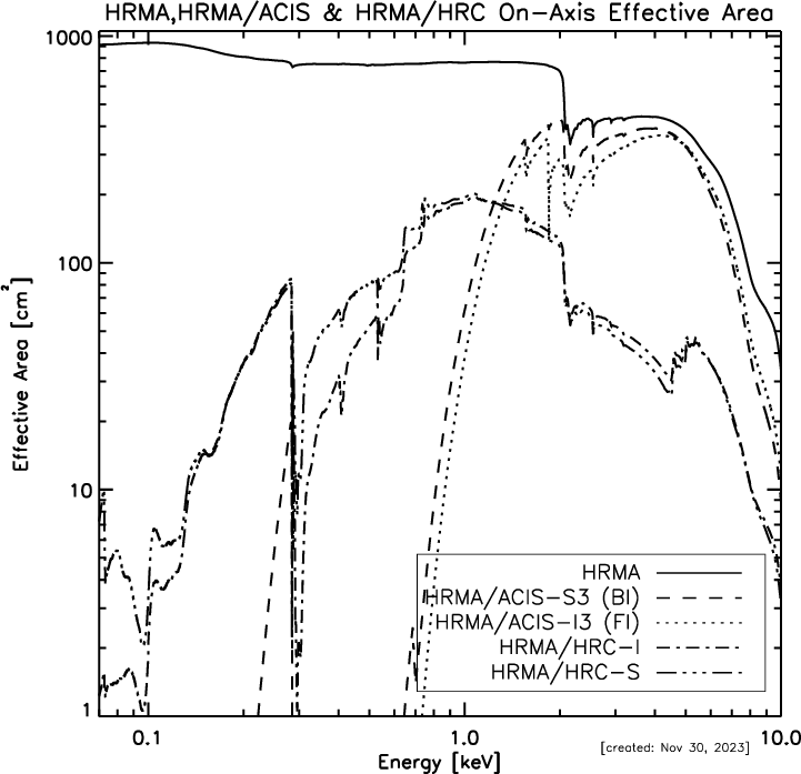
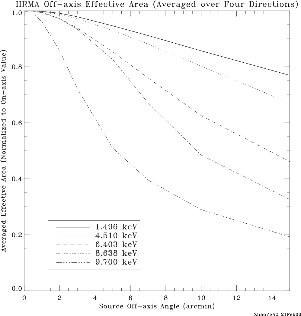
The combined HRMA/ACIS and HRMA/HRC effective areas released in CALDB 4.1.1 are shown in Figure 4.4 and the effect of off-axis vignetting on the HRMA effective area is shown in Figure 4.5 at several different photon energies. Note that this change in the effective area also serves to bring Chandra and XMM-Newton continuum measurements of cluster temperatures into closer agreement.
./images/hrma_ea_irm.png
Figure 4.2: Combined residuals from power-law fits to 18 blazar observations (Marshall 2005). The residuals in the upper panel are based upon models of contaminant free optics, while those in the lower are based upon a model of the mirror surfaces which includes a thin (22 Å) hydrocarbon layer.
./images/hrma_ea_olvd_modelF_d_pog.png
Figure 4.3: The HRMA Effective area: The top panel shows the raytrace prediction and the XRCF measurement data of the HRMA effective area as a function of energy. The bottom panel shows the ratio of the XRCF data to the raytrace. The raytrace includes the effects of molecular (CH2) contamination with variable thickness on the mirrors. The dotted line with error bars are the C-K continuum data, taken simultaneously with a solid-state detector (SSD). Data obtained from spectral line sources with a flow proportional counter (FPC) are shown as diamonds; those obtained with an SSD are shown as triangles. All the line measurements are circled for clarity. The solid (green) line in the bottom panel shows the XRCF empirical correction to the raytrace based on the XRCF data. The solid (green) line in the upper panel shows the absolute HRMA effective area with the XRCF empirical correction.
./images/hrma_ea_onaxis_qe.png

./images/hrma_ea_onaxis_qe_log.png
Figure 4.4: The HRMA/ACIS and HRMA/HRC effective areas versus X-ray energy in linear-linear (top) and log-log (bottom) scales. The structure near 2 keV is due to the iridium M-edge. The HRMA effective area is calculated by the raytrace simulation based on the HRMA model and scaled by the XRCF calibration data. The HRMA/ACIS effective area is the product of the HRMA effective area and the Quantum Efficiency (QE) of ACIS-I3 (front illuminated) or ACIS-S3 (back illuminated). The HRMA/HRC effective area is the product of HRMA effective area and the QE of HRC-I or HRC-S at their aimpoints, including the effect of UV/Ion Shields (UVIS). These figures are based upon the expected QEs at launch, and do not take into account any subsequent degradation or contamination while in orbit.
./images/hrma_ea_offaxis.png
Figure 4.5: The HRMA  effective area versus off-axis angle, averaged over four azimuthal directions, for selected energies, normalized to the on-axis area for that energy.

4.2.3  Point-Spread-Function and Encircled Energy Fraction

The Chandra HRMA point-spread function (PSF ) has been simulated with numerical raytrace calculations based upon the mirror model previously discussed. A most useful parameter is the encircled energy fraction (the two-dimensional integral of the PSF) as a function of radius from the image center. The PSF and the encircled energy fraction for a given radius depend upon off-axis angle and energy. The HRMA optical axis is defined for practical purposes as—and calibrated in flight to be—the direction of the sharpest PSF. The PSF broadens and the encircled energy fraction decreases as (1) the off-axis angle increases, because of mirror aberrations; and (2) the X-ray energy increases, because of increased X-ray scattering.

On-axis PSF

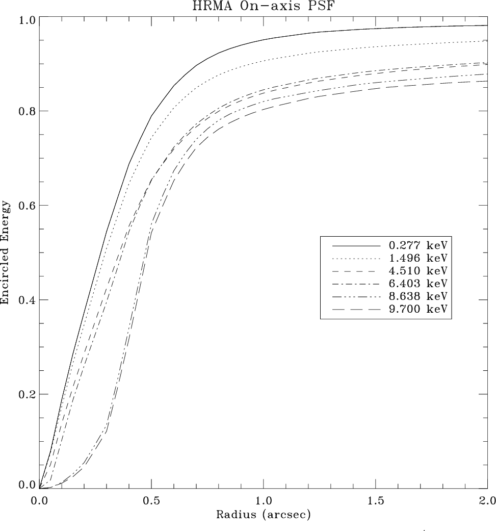
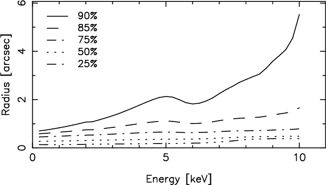
Figure 4.6 shows the encircled energy fraction as a function of image radius for an on-axis point source and for different energies. The resulting increase in image size with energy is apparent. Figure 4.7 shows the radii of selected encircled energy fractions as functions of energy for an on-axis point source. Table 4.2 lists the encircled energy fraction contained within one and ten arcsec diameters for an on-axis point source at different energies.
./images/hrma_psf_guide_fp.png
Figure 4.6: Fractional encircled energy as a function of angular radius, calculated for an on-axis point source, at selected X-ray energies. The curves are the combined response and centered at the common focus of the full HRMA, i.e. four nested mirror pairs. For higher energies (8.638 keV and 9.700 keV), the curves are broadened at small radii. This is because the focus of higher energies does not coincide with the HRMA common focus, but is offset by about 0.2 arcsec, due to a slight tilt of the HRMA mirror pair 6.
./images/hrma_ee.png
Figure 4.7: The radii of selected encircled energy fractions as functions of X-ray energy for an on-axis point source, calculated from the mirror model derived from ground-based calibration data.
Table 4.2: HRMA Encircled Energy Performance

X-ray:Encircled Energy Fraction
EλDiameter
keVÅ1 arcsec 10 arcsec
0.1085 114.2712 0.7954 0.9979
0.1833 67.6401 0.7937 0.9955
0.2770 44.7597 0.7906 0.9929
0.5230 23.7064 0.7817 0.9871
0.9297 13.3359 0.7650 0.9780
1.4967 8.2838 0.7436 0.9739
2.0424 6.0706 0.7261 0.9674
2.9843 4.1545 0.6960 0.9560
3.4440 3.6000 0.6808 0.9479
4.5108 2.7486 0.6510 0.9319
5.4147 2.2898 0.6426 0.9300
6.4038 1.9361 0.6365 0.9344
8.0478 1.5406 0.5457 0.9185
8.6389 1.4352 0.5256 0.9151
10.0000 1.2398 0.4971 0.8954
Pre-flight measurements and images taken at the XRCF show that there is a slight ( ≈ 500 μm) offset between the optical axes of the paraboloids and hyperboloids, and that pair 6 is slightly tilted with respect to the other three. Consequently, the image from mirror pair 6 is not as symmetrical as the images produced by the other shells. The effect of this asymmetry on images depends on energy because of the different relative contribution of mirror pair 6.
./images/hrma_hrc_onaxis_image_bw.png
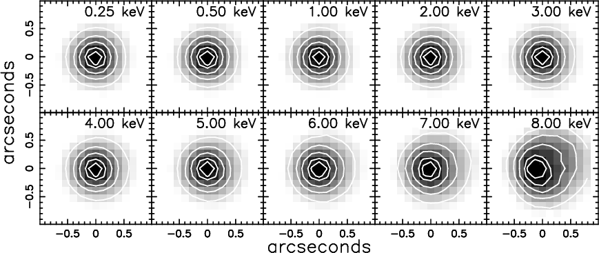
Figure 4.8: Simulated on-axis HRMA/HRC-I images of on-axis mono-energetic point sources with aspect blurring. The grayscale is a linear stretch; surface brightness contours are at 90%, 80%, 60%, 40%, and 20% of the peak brightness. The 8 keV image core is asymmetric and off-center due to the shell 6 misalignment.
Figure 4.8 shows simulated HRMA/HRC-I images at several energies. The effect of the mirror pair 6 alignment errors can be seen in the higher energy images as then mirror pair 6 becomes the dominant contributor to the total effective area. Note the movement of position of the core as well as the asymmetric flaring. The  ∼ 0.2 arcsec core motion is comparable to other factors of image degradation encountered in flight, such as uncertainties in the aspect solution.
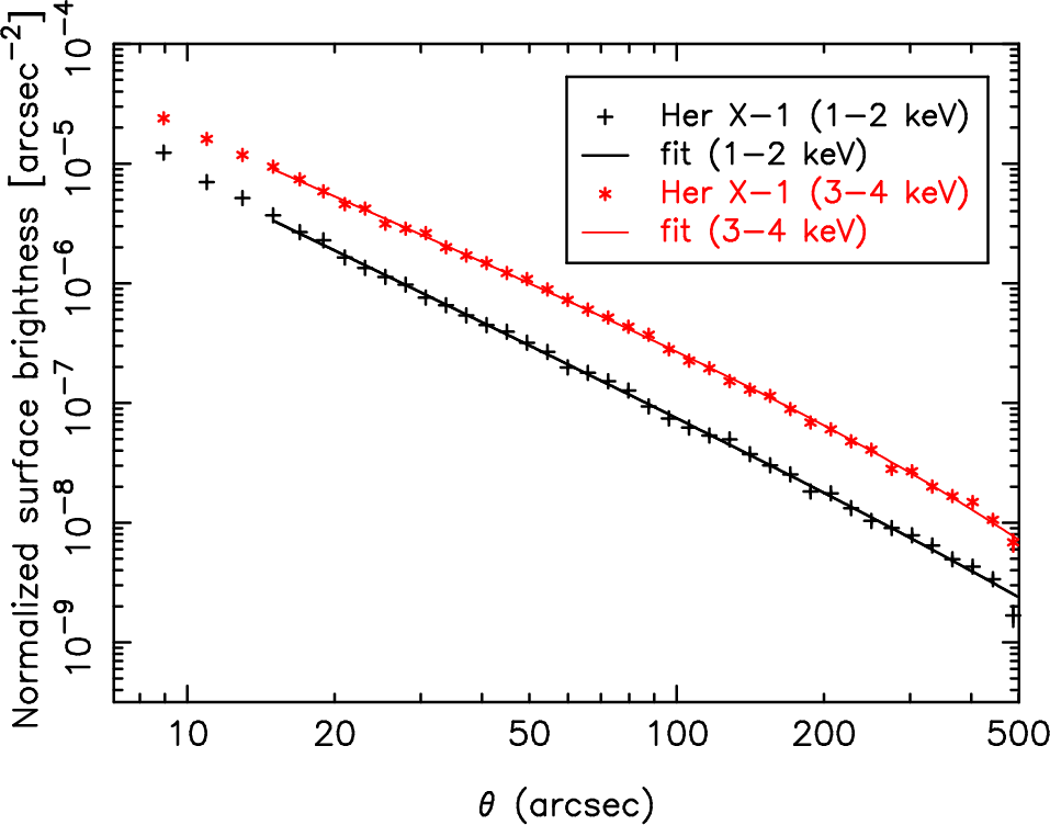
The HRMA PSF has a faint halo extending to large angles, resulting from X-rays scattering from micro-roughness on the mirror surfaces. This scattering is energy dependent; the spectrum of the scattered X-rays hardens significantly with increasing angle from the source. An empirical model was generated based on the ground calibration measurements; a number of systematic effects remain to be accounted for, and the uncertainties in the flux in the wings are probably at least 30 50%. This model is described more fully in https://cxc.harvard.edu/cal/Hrma/XRCF-Wings.html. A deep calibration observation of Her X-1 (ObsID 3662) was obtained in order to improve the understanding of the PSF wings. The SIM was shifted to move the optical axis to  ∼ 1 arcmin from the edge of the S3 detector furthest from the frame store; a Y-offset moved the image  ∼ 1 arcmin into node 0 of the detector. The resulting pointing is  ∼ 45 arcsec off-axis, effectively on-axis with regard to the mirror scattering properties. The analysis is discussed in more detail in https://cxc.harvard.edu/cal/Hrma/rsrc/Publish/ Optics/PSFWings/ wing_analysis_rev1b.pdf; see also https://cxc.harvard.edu/ cal/Hrma/UsersGuide.html.
./images/hrma_wings_both.png
Figure 4.9: Normalized radial profiles (units arcsec−2) of the Her X-1 scattering wings. The shapes are well determined beyond 15 arcsec, but the overall normalization may be uncertain by a factor of 2. The lower curve shows the 1.0 2.0 keV profile and the upper curve shows the 3.0 4.0 keV profile. In each case, the heavy solid line is a power-law plus exponential cutoff fit to the Her X-1 data.
Radial profiles of the Her X-1 scattering wings are plotted for energy bands 1.0 2.0 keV and 3.0 4.0 keV in Fig. 4.9. These are surface brightness profiles normalized by the source count rate estimated from the transfer streak spectrum. The units of the normalized profiles are in arcsec−2. A fit (power-law plus exponential cutoff) is over-plotted, and the fit applies for θ > 15 arcsec. Inside 15 arcsec, the profiles are increasingly depressed because of the effects of pile-up in this very bright source. The shape of the wing profile is well represented (beyond 15 arcsec), but the overall normalization may be off up to a factor of two.
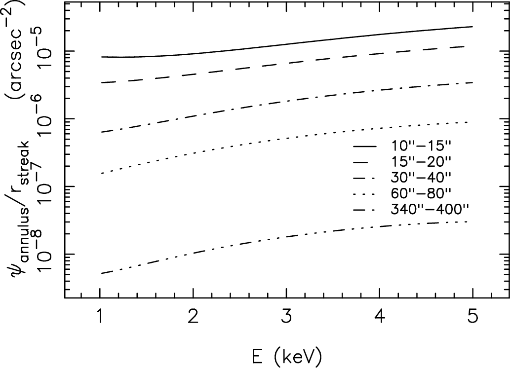
Because the mirror scattering is in part diffractive, the diffuse mirror scattering halo is energy dependent. Spectra extracted from the diffuse mirror scattering wings of the PSF are significantly modified from the spectrum of the incident source X-rays. Generally, the scattering halo spectrum becomes harder with increasing angle from the source. Fig. 4.10 shows the ratio of diffuse spectra extracted from annuli centered on the specular image of Her X-1 (normalized by extraction region area) to the corresponding spectrum extracted from the ACIS transfer streak for the source; the transfer streak spectrum is thought to be  ∼ 4% piled up.
./images/hrma_ann_over_xfrstreak.png
Figure 4.10: Hardening of the diffuse mirror scattering halo with distance from the direct image. The spectra for a number of annuli were normalized by the area of the extraction regions (taking into account chip edges) giving ψannulus cts s−1 keV−1 arcsec−2. These were each divided by a spectrum evaluated using the transfer streak events for the direct image, rstreak cts s−1 keV−1. The legend indicates annular radii in arcsec.

Off-axis PSF

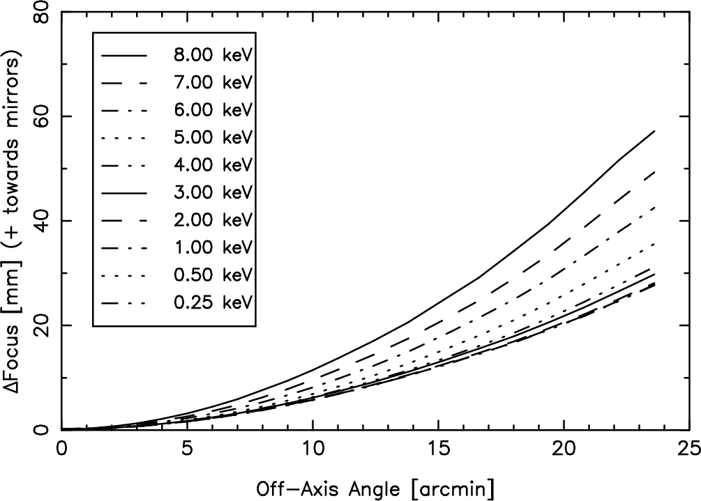
The PSF broadens for off-axis sources, and there is considerable distortion in the image even if the HRMA were perfect. This distortion is due to the aberrations of Wolter Type-I optics and to the different focal surfaces (Figure 4.11) for the four mirror pairs. The increase in image size with off-axis angle is greatest for the inner shell, and hence is larger for higher X-ray energies.
./images/hrma_focal_surface.png
Figure 4.11: The HRMA focal surface (from simulations), indicating its dependence on energy and off-axis source position.
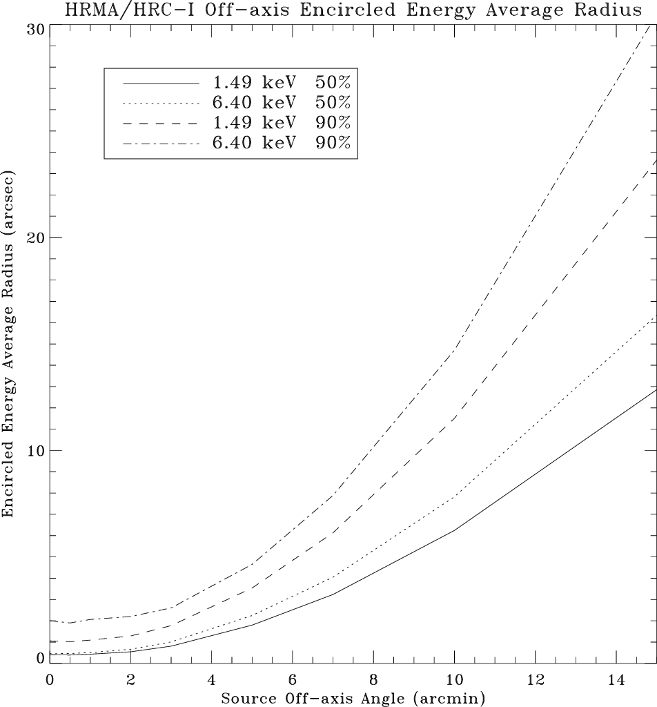
Figure 4.12 shows the dependence of encircled energy radii on off-axis angle on the HRC-I with the HRMA focus at the HRC-I aimpoint. Because the HRC-I is axially symmetric with respect to the HRMA optical axis, the off-axis encircled energy radii are almost azimuthally symmetric, except some small asymmetry due to the imperfect HRMA as mentioned above. The figure gives the averaged radii for 1.49 keV and 6.40 keV at 50% and 90% encircled energy. The blurs due to the HRC-I spatial resolution and the aspect solution, estimated to be FWHM =0.22 arcsec, are included.
./images/hrma_ee_offaxis_hrci.png
Figure 4.12: The HRMA/HRC-I  encircled energy average radii for circles enclosing 50% and 90% of the power at 1.49 and 6.40 keV as a function of off-axis angle. The HRC-I surface is a flat plane perpendicular to the optical axis, which does not follow the curved Chandra focal plane. These curves include the blurs due to the HRC-I spatial resolution and the Chandra aspect error.
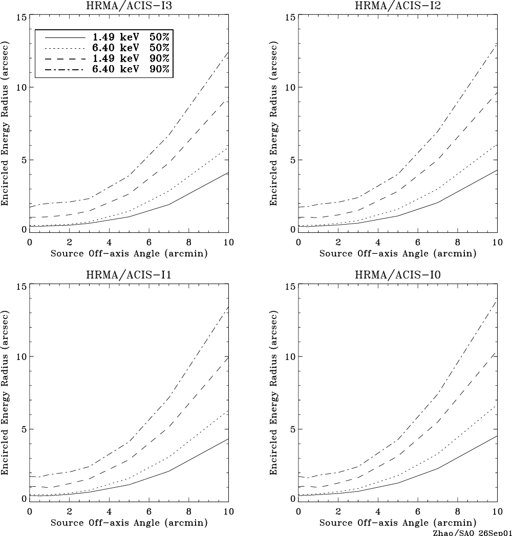
The ACIS-I surface is not axially symmetric with respect to the HRMA optical axis, because the HRMA aimpoint is located near the inner corner of one of the four ACIS-I chips: I3. Thus the off-axis encircled energy radii are not azimuthally symmetric. Figure 4.13 shows the dependence of encircled energy radii on off-axis angle on the four ACIS-I chips. The figure gives the encircled energy radii for 1.49 keV and 6.40 keV at 50% and 90% encircled energy in four azimuthal directions-from the aimpoint to the outer corners of the four ACIS-I chips. The blurs due to the ACIS-I spatial resolution and the Chandra aspect error are included.
./images/hrma_ee_offaxis_acisi.png
Figure 4.13: The HRMA/ACIS-I encircled energy radii for circles enclosing 50% and 90% of the power at 1.49 and 6.40 keV as a function of off-axis angle. The ACIS-I surface is composed by four tilted flat chips which approximate the curved Chandra focal plane. The HRMA optical axis passes near the aimpoint which is located near the inner corner of chip I3. Thus the off-axis encircled energy radii are not azimuthally symmetric. The four panels show these radii's radial dependence in four azimuthal directions-from the aimpoint to the outer corners of the four ACIS-I chips. These curves include the blurs due to the ACIS-I spatial resolution and the Chandra aspect error.
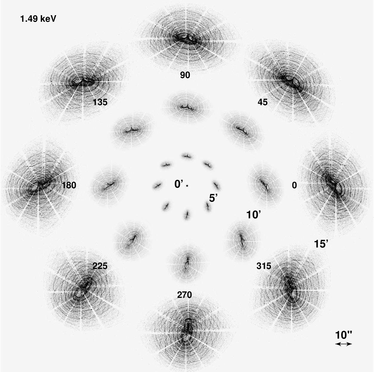
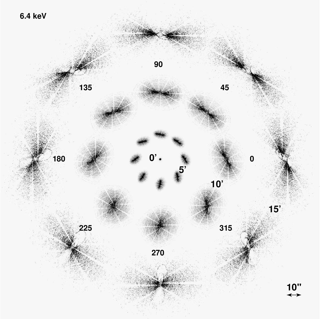
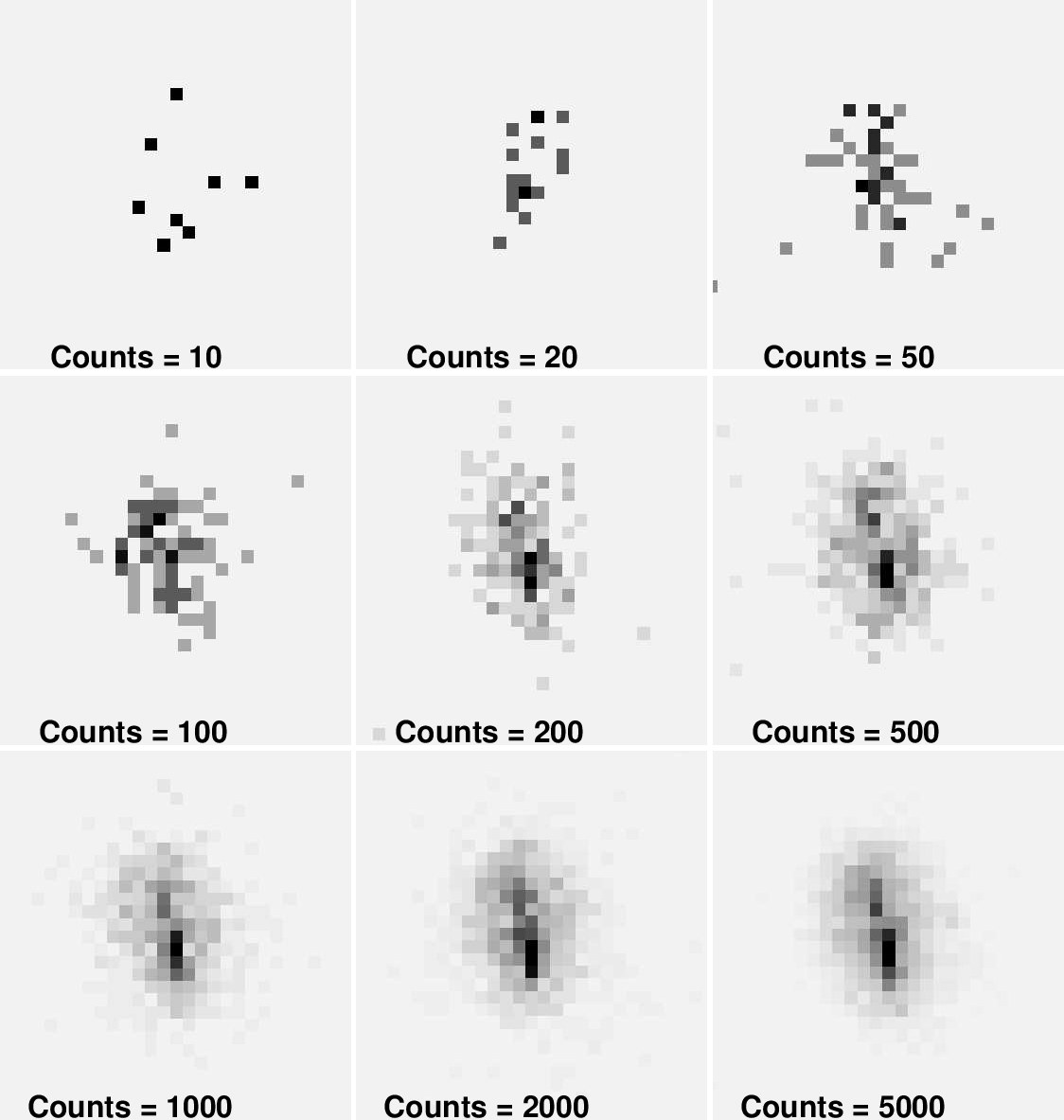
Figures 4.14 and 4.15 illustrate the effect of aberrations on images of off-axis point sources at 1.49 keV and 6.4 keV. The images are simulations of the HRMA alone, projected to the HRC-I detector plane. The degradation in image quality is primarily due to the separation between the detector plane and the effective focal plane, which is a strong function of both energy and off-axis angle (see Figure 4.11). Cusps in the HRMA images are due to a slight misalignment of the parabolic and hyperbolic mirrors. The signal in these figures is much higher than what might be expected in an actual observation. Figure 4.16 shows how the morphology of an off-axis image varies with the number of counts in the image. It is very easy to mistakenly conclude that an off-axis source is extended or has several components, even with a large number of counts.
./images/hrma_offaxis_image_1_49.png
Figure 4.14: Simulated 1.49 keV images, for the HRMA only. Images are shown with a linear stretch, as they would appear on the sky, at three off-axis angles (5 arcmin, 10 arcmin, and 15 arcmin) and various azimuths. The images are all to the same scale, illustrated by the scale bar. The spacing between images is arbitrary. The surface brightness of the images at 10 arcmin and 15 arcmin has been enhanced to show structure. Spokes in the images are due to shadowing by mirror support struts. Cusps are due to a slight misalignment of the parabolic and hyperbolic mirrors. These simulations are at an effective roll of zero-observations should be "de-rolled" before comparison to these images.
./images/hrma_offaxis_image_6_4.png
Figure 4.15: Simulated 6.4 keV images, for the HRMA  only. Images are shown with a linear stretch, as they would appear on the sky, at three off-axis angles (5 arcmin, 10 arcmin, and 15 arcmin) and various azimuths. The images are all to the same scale, illustrated by the scale bar. The spacing between images is arbitrary. The surface brightness of the images at 10 arcmin and 15 arcmin has been enhanced to show structure. Spokes in the images are due to shadowing by mirror support struts. Cusps are due to a slight misalignment of the parabolic and hyperbolic mirrors. These simulations are at an effective roll of zero-observations should be "de-rolled" before comparison to these images.
./images/hrma_offaxis_image_1_49_confusion.png
Figure 4.16: A simulated 1.49 keV point source at an off-axis angle of 5 arcmin, binned to ACIS pixels. The panels show what the source would look like with a varying number of counts. Note how the apparent morphology is a strong function of the number of counts, and how even with a large number of counts one might mistake it for an extended source or even for multiple sources.

PSF Stability

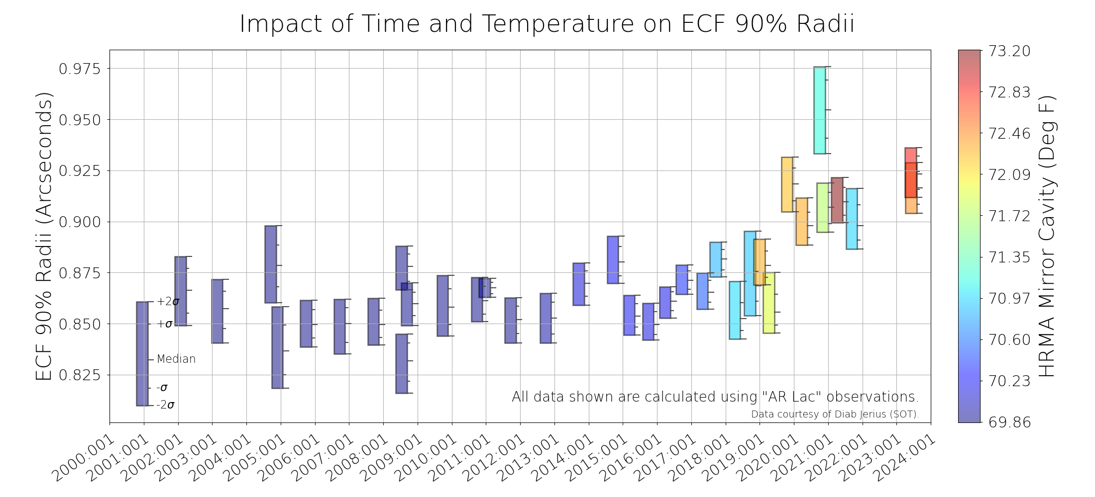
The Chandra PSF stability has been measured over the mission via annual on-axis observations of AR Lac with HRC-I. The measured statistic is the radius enclosing 90% of the counts from the source (Enclosed Count Fraction, or ECF). The HRMA temperature has not been immune to the degradation of thermal control of the telescope, but impacts on the PSF are small and do not impact science (see Figure 4.17).
./images/hrma_thermal_ecf90_time.png
Figure 4.17: Evolution of the HRMA 90% ECF over time and its relationship to the HRMA cavity temperature. Measurements are useful only for relative longitudinal comparisons.

PSF Anomalies

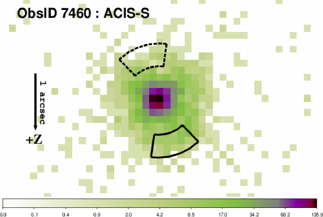
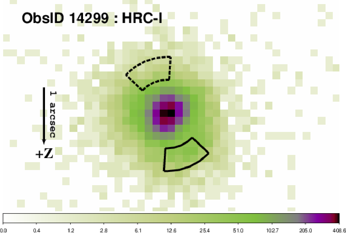
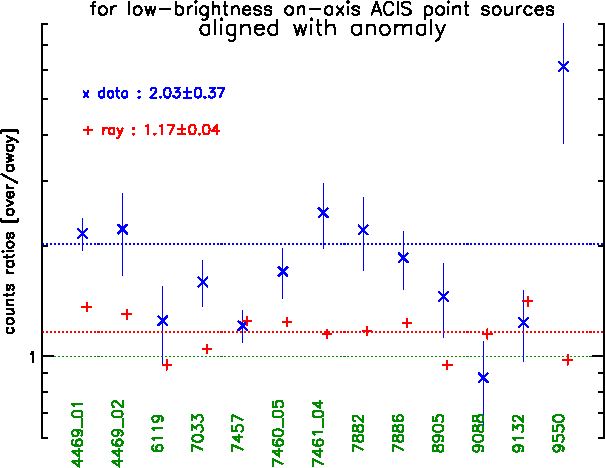
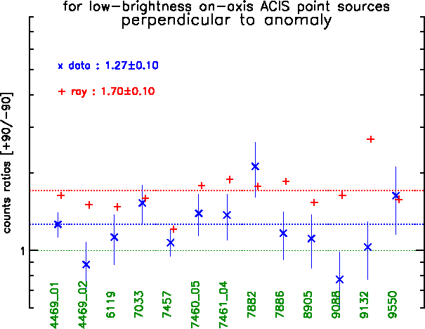
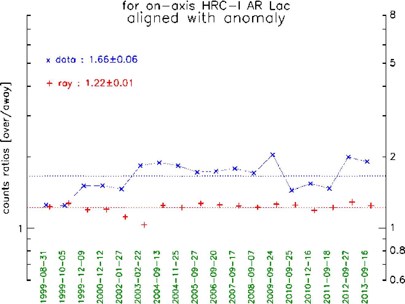
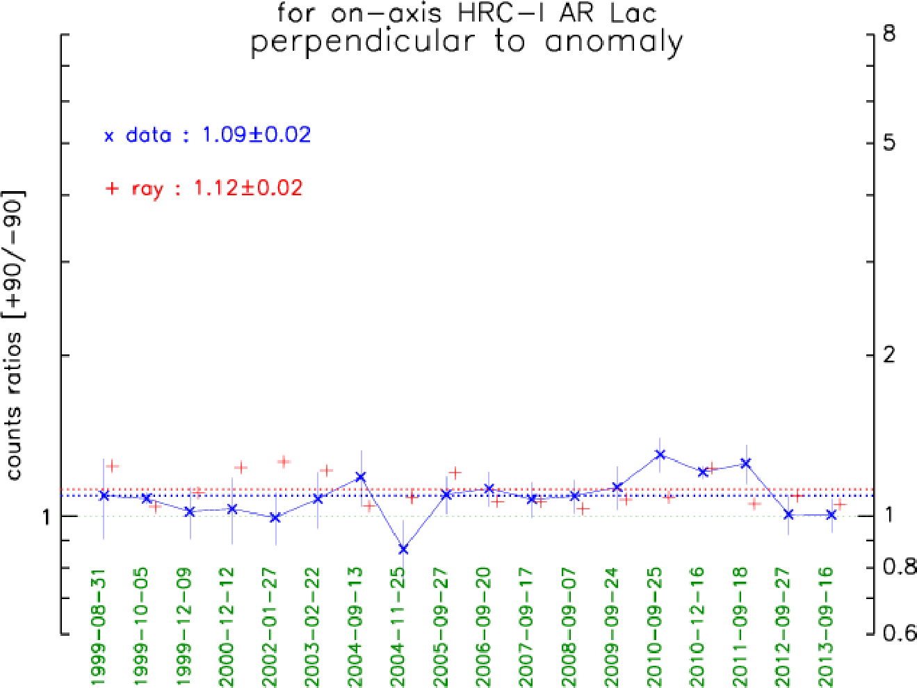
An anomaly was discovered in the observed PSF during deconvolution of on-axis HRC-I observations of AR Lac and Capella (Juda & Karovska 2010; see §7.6). The images showed hook-shaped residuals that developed c.2003. The anomalous features are located ≈ 0.8 arcsec from the centroid, towards mirror spherical coordinate, φ = 285±25 (see the CIAO caveats page https://cxc.harvard.edu/ciao/caveats/psf_artifact.html), slightly offset from the spacecraft +Z direction (see Figure 1.2). The existence of an asymmetry in the PSF profile, consistent with the HRC results, was subsequently verified with ACIS data of low count-rate, high-exposure, on-axis point sources (Kashyap 2010; see also §6.6.1). This anomaly, apparent as an asymmetry in the profile of the PSF (see Figures 4.18,4.19,4.20), is as yet unexplained and cannot be modeled with raytraces. Modeling of jets or other structure in the source aligned along this direction will be affected by this anomaly.
images/hrma_anomaly_aciss_7460.png
images/hrma_anomaly_hrci_14299.png
Figure 4.18: The PSF anomaly, illustrated with ACIS-S (top) and HRC-I (bottom) images. The ACIS-S image is of a Low Mass X-ray Binary in NGC 6397, and the HRC-I image is of AR Lac. The ACIS image is binned at [1/4] sky-pixel resolution, similar to the HRC resolution. The datasets have been derolled such that the spacecraft +Z axis points vertically down (indicated by a vertical arrow of length 1 arcsec). The part of the PSF that is affected by the anomaly is shown by the pie-shaped region (solid boundary) computed with the CIAO tool make_psf_asymmetry_region. The same region, rotated diametrically across from image centroid is also shown (dashed boundary) for comparison. The asymmetry in the counts in the two regions is apparent; there are more counts within the region located over the anomaly than in the region away from the anomaly.
images/cf_anomaly_ratios_acis_align2-crop.png

images/cf_anomaly_ratios_acis_perp2-crop.png
Figure 4.19: The ratio of counts collected from different segments around the PSF for a number of low-count-rate on-axis point sources (see Kashyap 2010). These are sources for which pile-up effects are minimal, and which have no previously known intrinsic features. The counts are collected in pie-shaped regions over and away from the anomaly (top; see Figure 4.18) and from similar regions rotated ±90° from them (bottom). The ratios for counts are shown for both the data (`x'; blue points) and raytrace (`+'; red points). The error bars are shown as thin vertical lines. The average of the ratios computed for all the sources are also shown, along with the standard errors on the mean. There is a clear asymmetry in the PSF profile of the data along the nominal direction of the anomaly that is neither present in the perpendicular direction, nor accountable by raytraces. Comparison with the raytrace model PSFs is necessary to establish the reality of the anomaly, since the Chandra PSF is not azimuthally symmetrical and displays intrinsic asymmetries. See, for instance, the ratios along the perpendicular direction, in the lower figure, where they are higher for the raytrace model than for the data, signifying that there are as yet unexplained differences between the data and the raytrace model. The mechanism by which these discrepancies arise is under investigation.
images/cf_anomaly_ratios_hrci_align2.png
images/cf_anomaly_ratios_hrci_perp2.png
Figure 4.20: As Figure 4.19, for on-axis HRC-I observations of AR Lac. Notice that the magnitude of the anomaly was low early in the mission and appears to be fully formed by 2003-Feb. There are also indications that the asymmetry was reduced between late-2010 and late-2011. The raytrace PSF model for the HRC includes smoothing due to detector blur.

4.3  Ghost Images

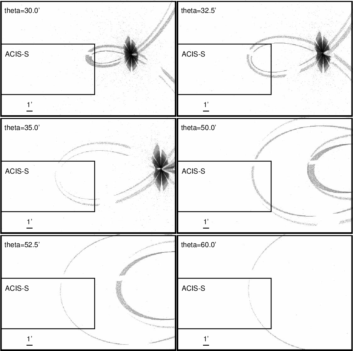
Baffles prevent non-reflected or singly reflected photons from impinging on the focal plane within the central 30 arcmin diameter region of the field of view. Outside of this region, however, singly reflected photons from strong off-axis sources may appear. The spray of singly reflected photons is faint relative to the direct image, but can be quite complex. Each individual paraboloidal or hyperboloidal mirror can generate its own single-reflection ghosts. These form loops sweeping in toward the center of the focal plane as the source off-axis angle increases. The ghost loops from the smallest mirrors are the first to approach the central regions as source off-axis angle increases. With increasing source off-axis angle, the large mirrors come into play. As a loop approaches the central 30 arcmin diameter region of the field of view, the inner parts of the loop fade and break up.
These single-reflection ghosts can impinge on the detector even if the source itself does not fall within the detector field of view. These ghosts mainly affect the outermost portions of those detectors which extend to large off-axis angles: HRC-I, and the spectroscopy arrays, HRC-S and ACIS-S. Figure 4.21 shows simulated ghost images on the ACIS-S array. Point sources were simulated at a range of off-axis angle θ and at a fixed off-axis azimuth (φ = 5°). The effects discussed above (e.g. fading of the loops as they approach the central field) can be seen in comparing the ghosts in the 30 arcmin-32.5 arcmin-35 arcmin sequence, or in the 50 arcmin-52.5 arcmin sequence.
./images/hrma_ghost_aciss_mosaic_150dpi.png
Figure 4.21: Simulated images of off-axis sources. The off-axis angle, theta (θ, in arcmin), is indicated, and all simulations were performed for the same value of φ (5°). The rectangle indicates the footprint for one end of the ACIS-S detector. These simulations illustrate how singly reflected photons can hit the detector even when the specular image is well outside the field of view. The surface brightness of these ghosts is low relative to the brightness of the X-ray sources, but could be relevant in planning observations near extremely bright X-ray sources.
Imaging observations with HRC-I or spectroscopy observations with HRC-S or ACIS-S which are near very bright sources can be checked using Chandra Ray Tracer (ChaRT) or Model of AXAF Response to X-rays (MARX) raytraces to determine whether single-reflection ghost images are likely to be a problem.

4.4  Effects of Aspect and Instrument Uncertainties

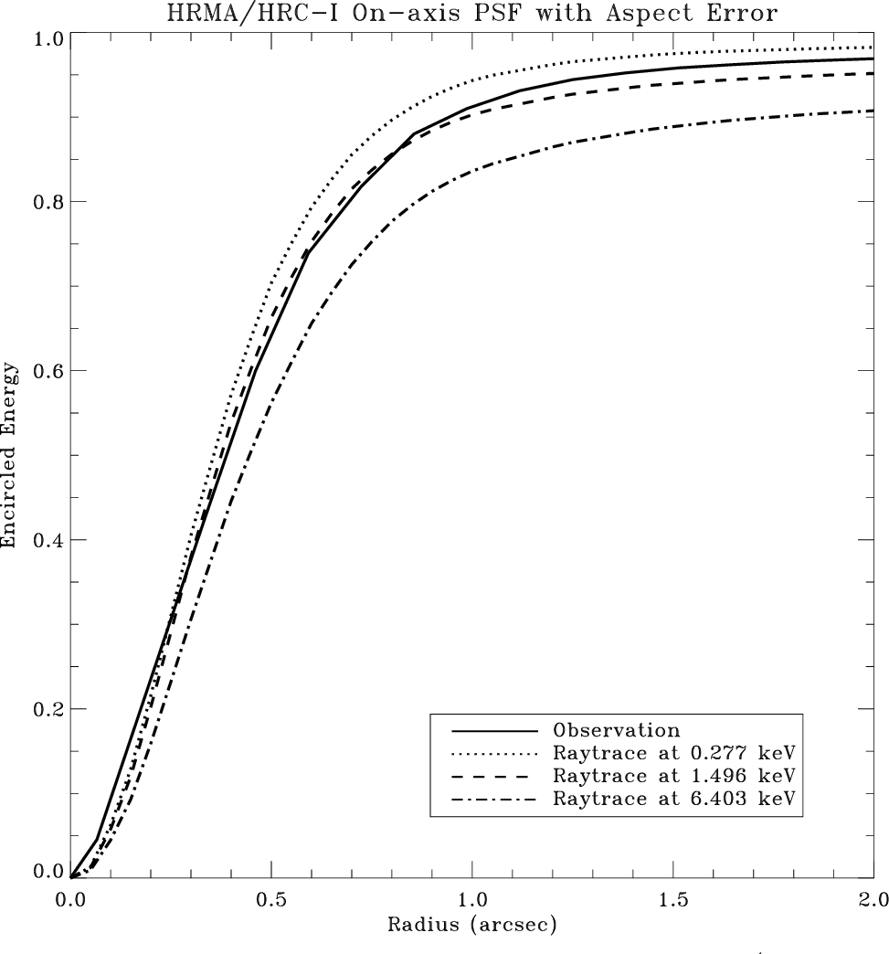
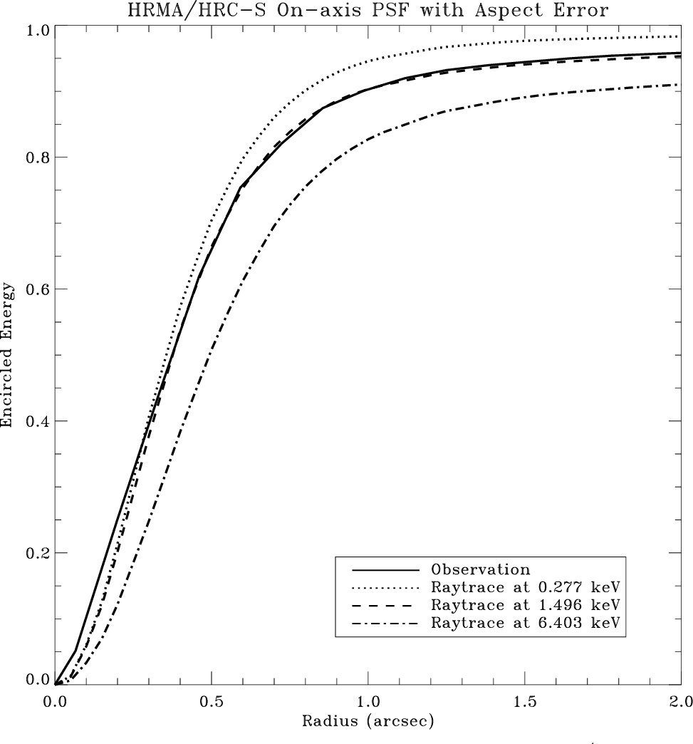
The HRMA performance discussed in the previous sections will be slightly degraded by uncertainties in the aspect solution and the details of the imaging detector spatial response function. The ground software system also deliberately adds a small random position error to reduce image artifacts which result from instrument and data system integer location values. The randomization may be turned off in data processing if desired. These effects are illustrated for the HRC-I and HRC-S instruments in Figures 4.22 and 4.23 respectively. These figures also show the fractional encircled energy as a function of radius actually observed in flight compared to model calculations at 0.277, 1.496, and 6.403 keV. An aspect error of 0.22 arcsec (FWHM) was included in the model calculations. The observed encircled energy curve most resembles that calculated for a monoenergetic source at 1.5 keV because this is typically the energy of the average detected photon.
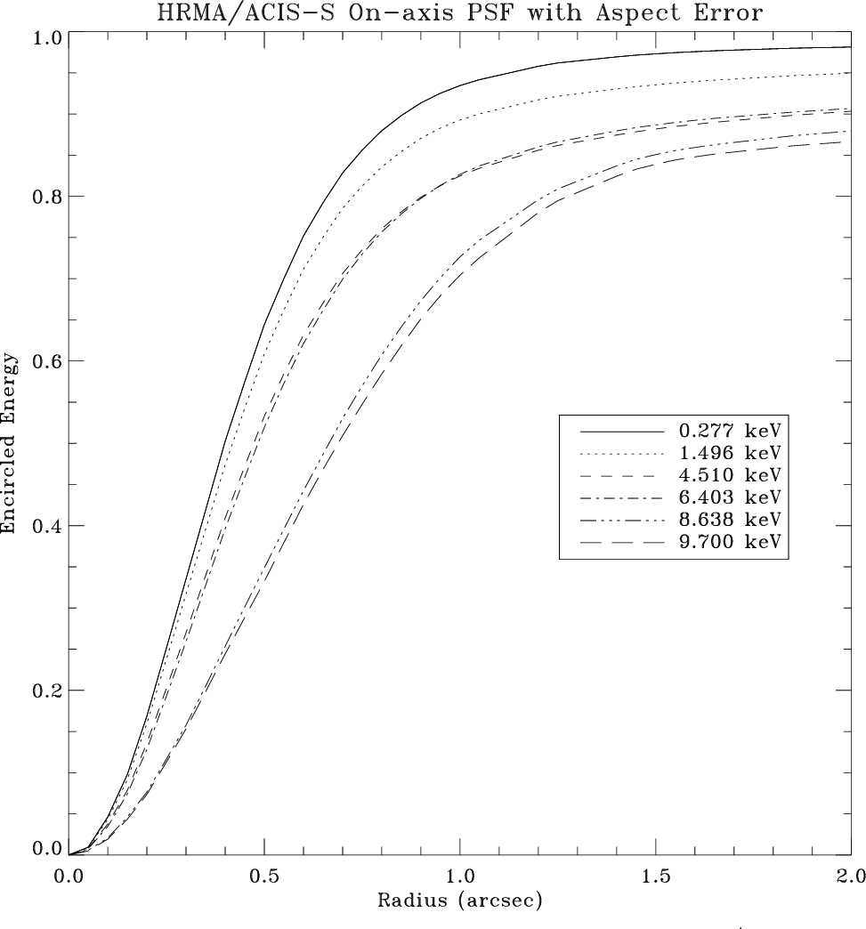
Similar calculations have been performed for the ACIS-S (S3) over a wider range of energies; the results are shown in Figure 4.24. The simulation accounted for the typical spacecraft jitter, so the location of the instrument pixel boundaries has little effect. There is, however, a small effect of the location of the source compared to the data system pixel boundaries. These particular calculations were performed for a point source centered on the boundary between two data system pixels. The ACIS-I instrument response is similar.
Figures 4.22, 4.23, and Figures 4.22, 4.23, and 4.24 may be compared with Figure 4.6 to estimate the image performance degradation due to non-HRMA effects.
./images/hrma_ee_aspect_hrc_i_point_obs_guide.png
Figure 4.22: The HRMA/HRC-I on-axis fractional encircled energy as a function of angular radius from a point source (Ar Lac) observed in flight compared to raytrace simulations for an on-axis point-source at selected X-ray energies, including the aspect uncertainties and the HRC-I pixelization effects.
./images/hrma_ee_aspect_hrc_s_point_obs_guide.png
Figure 4.23: The HRMA/HRC-S on-axis fractional encircled energy as a function of angular radius from a point source (LMC X-1) observed in flight compared to raytrace simulations for an on-axis point-source at selected X-ray energies, including the aspect uncertainties and the HRC-S pixelization effects.
./images/hrma_ee_aspect_acis_s_01_point_guide.png
Figure 4.24: The fractional encircled energy as a function of angular radius expected for in flight ACIS-S (S3) measurements for an on-axis point-source at selected X-ray energies. The curves are the combined response of the four nested mirror pairs, typical aspect uncertainties, and the ACIS response function.

ACIS PSF Broadening at Low Energies

There is some evidence that the soft ACIS PSF (up to  ∼ 800 eV) has been broadening since 2015. This broadening is discussed in more detail in Section 6.6.2.

4.5  Optical Axis and Aimpoint

Tracking the positions of the Chandra optical axis and aimpoint with respect to the detectors is the most relevant measurement for understanding the telescope stability. This section explains the properties of the telescope optical axis, aimpoint, and their drifts during the mission along with the measurements taken to mitigate the potential misalignments caused by these factors to ensure optimal imaging resolution and a successful mission.

4.5.1  Definitions

For ideal mirrors, the optical axis intersects the focal plane at the best focus which is both the focal point and the aimpoint. For the actual HRMA, the focal point and the aimpoint are not the same, although they differ only slightly. With respect to a preset coordinate system associated with each detector, the positions of both points have been drifting slowly since launch. The focal point (i.e. optical axis) drift is due to the alignment between the HRMA and the focal plane instruments. The aimpoint drift is due to the alignment between the HRMA and ACA.

4.5.2  Aimpoint on Chandra Detectors

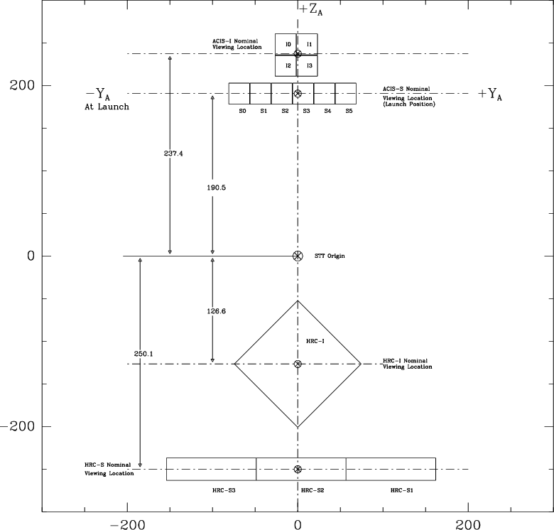
For each Chandra observation, one of four Chandra detectors is aligned with the HRMA optical axis by moving the entire Science Instrument Module (SIM) to that detector's nominal SIM-Z position. Figure 4.25 shows the layout of Chandra detectors in the SIM plane with the aimpoints indicated at their nominal positions.
./images/simc.png
Figure 4.25: Layout of Chandra Detectors: The schematic of the SIM plane shows the Chandra focal plane instrument to scale (mm). SIM +Y is along the x-axis; SIM +Z is along the y-axis. ⊗ on each detector marks the aimpoint position with nominal SIM-Z position and zero pointing offset.

4.5.3  Optical Axis

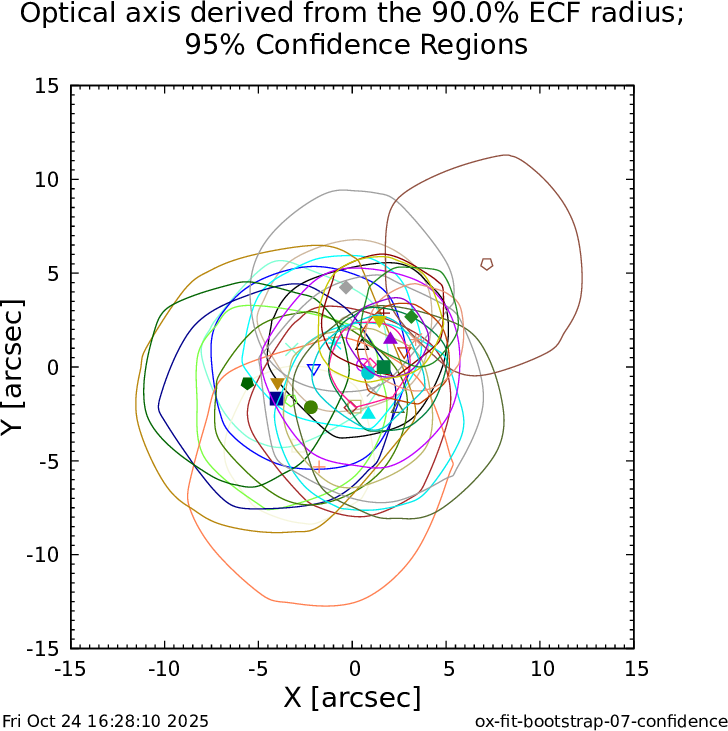
The optical axis position is derived from the semi-annual annular scan observations of Ar Lac, an eclipsing RS CVn binary star, using the HRC-I detector. An annular scan is a set of observations with one exposure at the aimpoint and a set of exposures on rings centered at the aimpoint and with 1, 2, 3, 4, and 6 arcmin radial offsets at 45° azimuthal increments for a total of 42 observations each year. 21 of them were carried out every half year and with 45° azimuthal offset from each other. The optical axis is determined by fitting the encircled energy radii determined from each annular scan observation with a 2-dimensional quadratic function in detector coordinates. By definition, the focal point is where the quadratic function is at its minimum and the optical axis goes through this point. Figure 4.26 shows all the optical axis positions so determined since the Chandra launch. They are quite stable, staying well within a 10 arcsec region and consistent with the measurement errors. This indicates that the optical bench connecting the HRMA and the SIM is rigid and the alignment between the two is very stable. The HRMA PSF and therefore the superb Chandra imaging resolution has been consistent since the Chandra launch.
./images/HRC_I_CHIP_opt_axis_7_202109.png
Figure 4.26: Chandra optical axis positions on HRC-I since launch. Each position is labeled by the year-month. The optical axis position is very stable and well within a 10 arcsec region.
./images/HRC_I_CHIP_opt_axis_6_202109.png
Figure 4.27: The same as Figure 4.26, with the 1-σ measurement error ellipse around each position for that given year. The drift of optical axis position is consistent with the measurement errors.

4.5.4  Permanent Default Aimpoints (PDA)

The target acquisition is achieved by first pointing Chandra's optical telescope (ACA) to a coordinate based on the telescope roll angle and with a known offset from the target position. Since this offset is fixed, the X-ray telescope (HRMA) should then be pointing to the target. However, because of the thermal changes in the alignment between the HRMA and the ACA, the Chandra effective aimpoint has been drifting slowly around the SIM[-Y,-Z] direction by a few arcsec each year since launch. Before Cycle 18, this drift was mitigated by setting default aimpoints on ACIS-I and ACIS-S using yearly updated point offsets. Starting with Cycle 18 observations, a permanent default aimpoint (PDA) is chosen for each detector. These PDAs are close enough to the optical axis so the PSFs are as sharp as on the optical axis while also far from the chip edges or node boundaries.
A predictive thermal model of the alignment between the ACA reference frame and HRMA is used in the planning process to compensate the pointing. However, due to residual uncertainties in this model, error boxes are given around each PDA, indicating the current pointing uncertainty. The dynamical aimpoint adjustment started on 2016-Aug-29. This process has improved the effective aimpoint stability.
The error box sizes are based on the observations taken on all the detectors during the 6 month period prior to 2021-Oct. The peak to peak swings of the short term fluctuations are 16 arcsec in the SIM +Y direction and 12 arcsec in the SIM +Z direction.
Observers also have the option to request the Y-offset, Z-offset and SIM-Z offset to put their targets at different locations on the detector. These offsets will be calculated from the PDA. Observers can use ObsVis to visualize the target location on the detectors with their chosen offsets. However, the error boxes will be the same size around their chosen location.
Table 4.3: Optical Axis & PDA Locations
DetectorChipSIM-Z Optical Axis [pixel] PDA [pixel]
[mm] ChipX ChipY ChipX ChipY
ACIS-I I3 −233.587 961.1±3.1 977.2±3.1 953.74 958.74
ACIS-S S3 −190.143 234.6±3.1 509.1±3.1 193.74 520.00
HRC-I 126.983 7610.7±15.8 7761.5±3.4 7590 7745
HRC-S S2 250.466 2163.6±11.4 8911.1±11.4 2195 8915

4.5.5  Optical Axis and PDA positions

The current optical axis and PDA locations are listed in Table 4.3. These numbers are used in CIAO and ObsVis.
On-axis targets will be imaged near the PDA and inside the error box on each detector. Observers should use this table to check their target location and may request different pointing offset based on their sources to maximize the scientific return. If the observer does not request a specific pointing offset, their target will be put near the PDA.
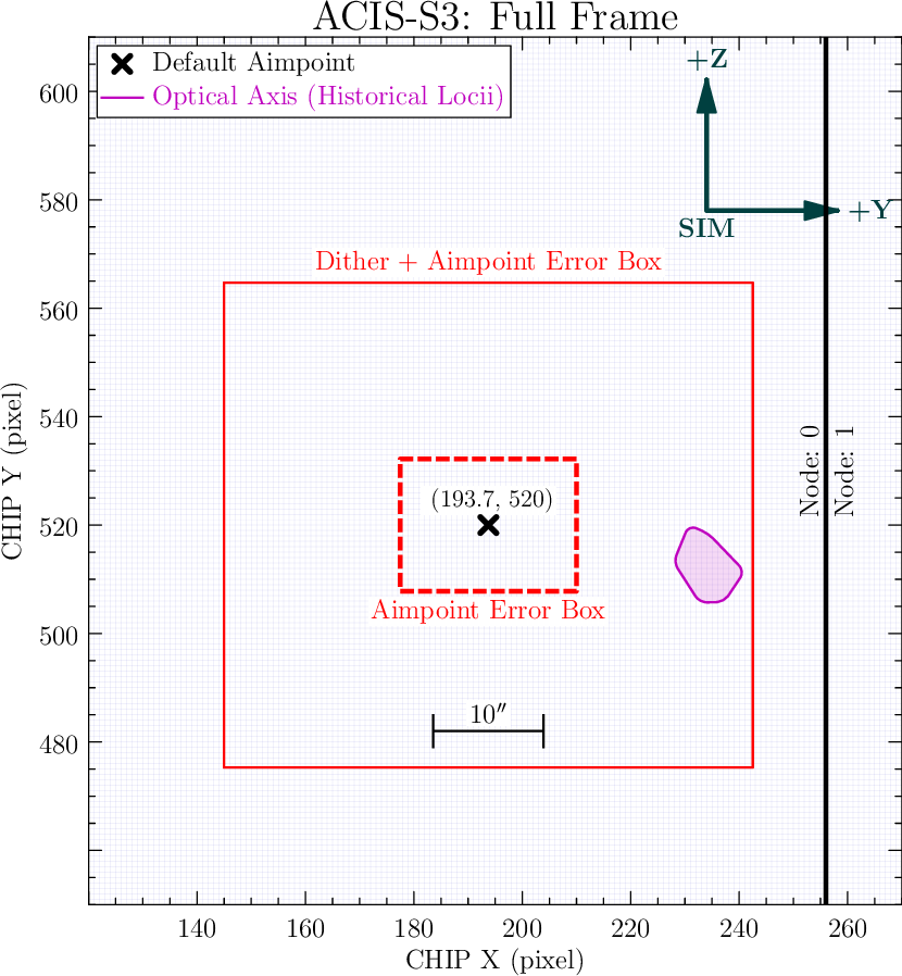
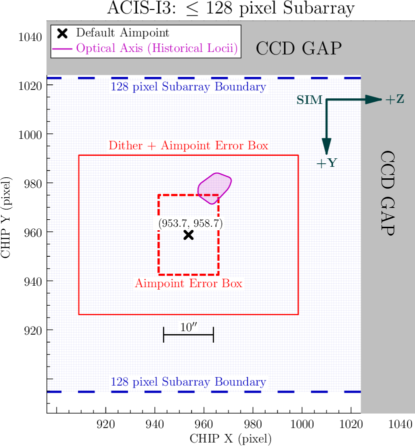
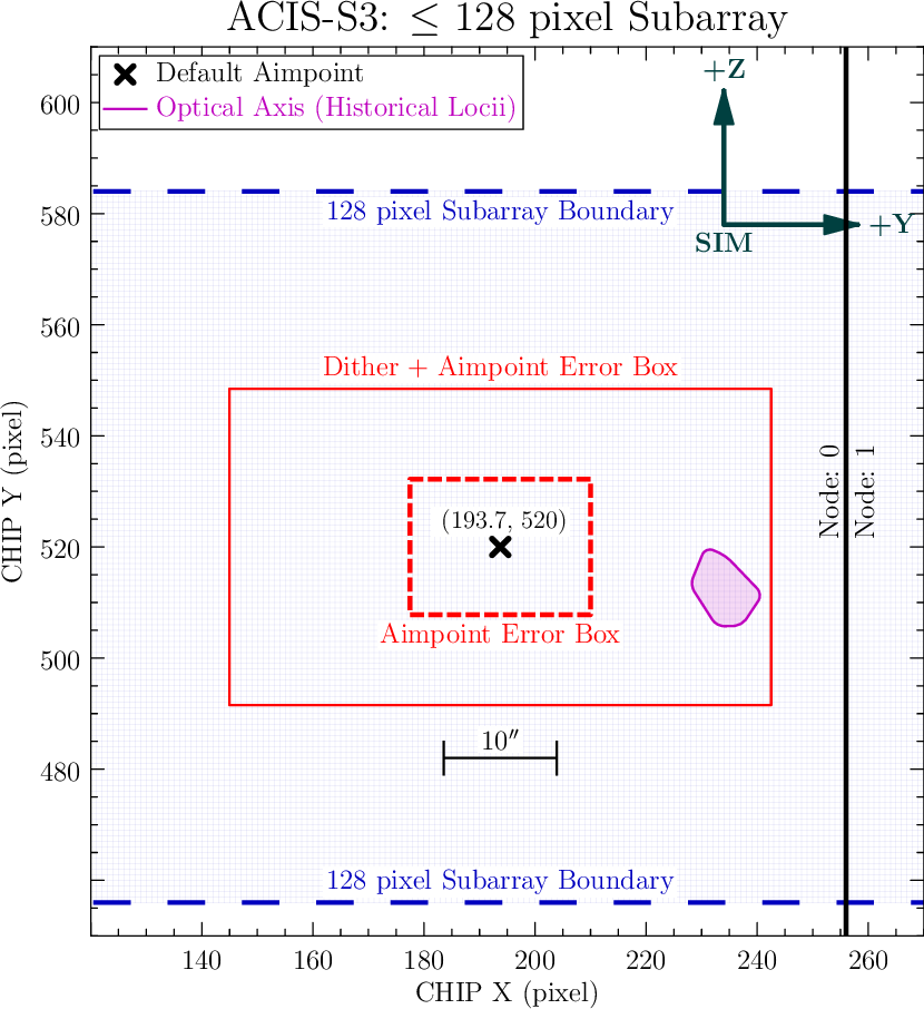
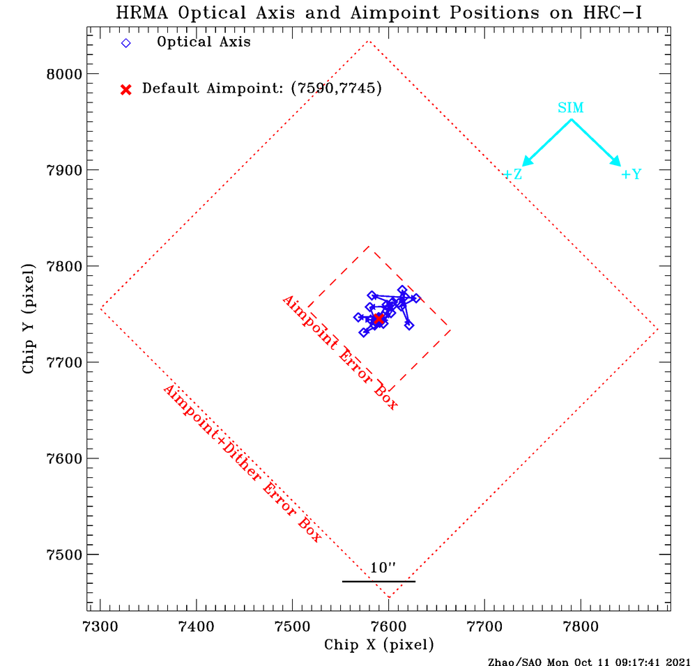
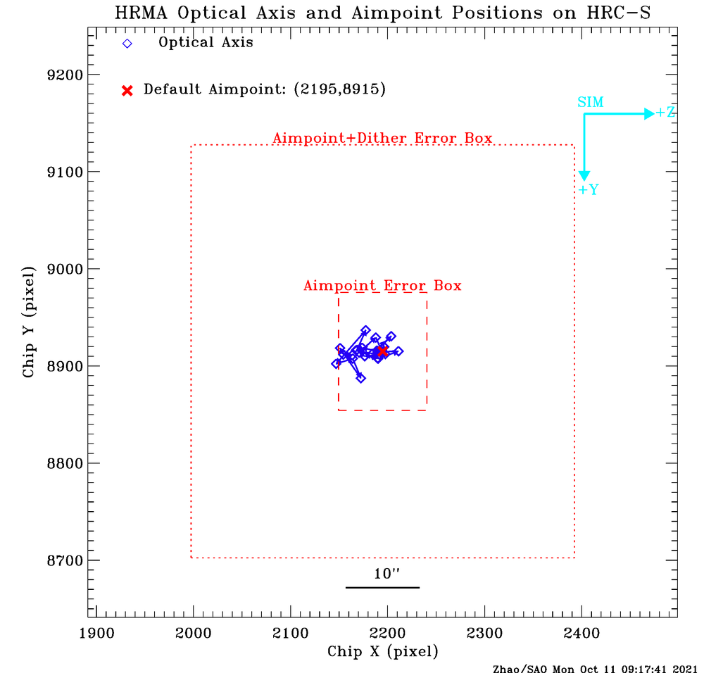
Telescope dither is used to reduce pileup and protect detectors from damage from bright sources. The dither pattern used for the ACIS detectors has been enlarged in Cycle 24 to improve background analysis for the PCAD system (the HRC dither pattern extent is already sufficient). When planning an observation, it is important to take into account the pointing uncertainty in addition to the dither extent to ensure that targets are located appropriately with respect to chip edges and ACIS node boundaries. Table 4.4 provides dimensions for the dither boxes (which include aimpoint error). Note that the dither patterns (and thus the dither boxes) differ for sub-arrays ≤ 128 pixels in order to ensure that dither in the short direction of the sub-array does not move targets out of the active region of the detector.
Figures 4.28 - 4.33 show the optical axis and PDA with their error boxes on all four detectors.
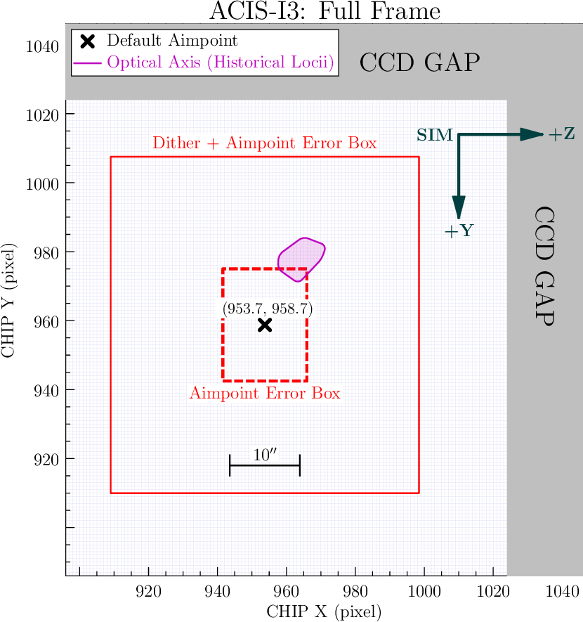
Table 4.4: Dimensions of Pointing Error & Total Dither Boxes
DetectorCoordsPointing Error Box Frame SizeTotal Dither Boxf
[′′] [pixel] [′′] [pixel]
ACIS-IChip X,Y 12" × 16"24.4 × 32.5Full 44" × 48"89.44 × 97.56
Sub > 128
Sub ≤ 128 44′′×32′′ 89.44×65
ACIS-S Chip X,Y 16" × 12" 32.5 × 24.4Full 48" × 44" 97.56 × 89.44
Sub > 128
Sub ≤ 128 48′′×28′′ 97.56×56.9
HRC-I SIM Y,Z 16′′×12′′ 121.4×91.1 Full 56′′×52′′ 425.0×394.7
HRC-S Chip X,Y 12′′×16′′ 91.1×121.4 Full 52′′×56′′ 394.7×425.0
f Includes pointing error
./images/ACIS-I3.png
Figure 4.28: ACIS-I3 Full-Frame PDA & Dither Box. The Chandra historical optical axis locii are represented by the purple blob; the Permanent Default Aimpoint (PDA) by the black cross. The smaller red dashed-line box centered at the PDA is the error box of the effective aimpoint center-an on-axis target can be anywhere inside this box. The larger red solid-line box contains the dither pattern convolved with the error box.
./images/ACIS-S3.png
Figure 4.29: ACIS-S3 Full-Frame PDA & Dither Box. The Chandra historical optical axis locii are represented by the purple blob; the Permanent Default Aimpoint (PDA) by the black cross. The smaller red dashed-line box centered at the PDA is the error box of the effective aimpoint center-an on-axis target can be anywhere inside this box. The larger red solid-line box contains the dither pattern convolved with the error box. The PDA is shifted  ∼ 12 arcsec from the optical axis to avoid the node boundary 0|1.
./images/ACIS-I3_subarray.png
Figure 4.30: ACIS-I3 Dither Box on a subarray ≤ 128 pixels. The Chandra historical optical axis locii are represented by the purple blob; the Permanent Default Aimpoint (PDA) by the black cross. The smaller red dashed-line box centered at the PDA is the error box of the effective aimpoint center-an on-axis target can be anywhere inside this box. The larger red solid-line box contains the dither pattern convolved with the error box.
./images/ACIS-S3_subarray.png
Figure 4.31: ACIS-S3 Dither Box on a subarray ≤ 128 pixels. The Chandra historical optical axis locii are represented by the purple blob; the Permanent Default Aimpoint (PDA) by the black cross. The smaller red dashed-line box centered at the PDA is the error box of the effective aimpoint center-an on-axis target can be anywhere inside this box. The larger red solid-line box contains the dither pattern convolved with the error box.
./images/hrci_opaxaimp_cor_shift26_2021.png
Figure 4.32: Chandra optical axis (blue diamonds) positions for each year and permanent default aimpoint (red cross) on HRC-I at [7590,7745]. The small box (red dashed line, 16 arcsec × 12 arcsec, or 121.4×91.1 pixels in SIM [Y, Z]) centered at the permanent default aimpoint is the error box of the effective aimpoint center, i.e. an on-axis target can be anywhere inside this box. The large box (red dotted line, 56 arcsec × 52 arcsec, or 425.0×394.7 pixels in SIM [Y, Z]) is the error box of effective aimpoint with dither.
./images/hrcs_opaxaimp_cor_shift26_2021.png
Figure 4.33: Chandra optical axis (blue diamonds) positions for each year and permanent default aimpoint (red cross) on HRC-S at [2195,8915]. The small box (red dashed line, 12 arcsec × 16 arcsec, or 91.1×121.4 pixels) centered at the permanent default aimpoint is the error box of the effective aimpoint center, i.e. an on-axis target can be anywhere inside this box. The large box (red dotted line, 52 arcsec × 56 arcsec, or 394.7×425.0 pixels) is the error box of effective aimpoint with dither.
More details of this topic can be found at https://cxc.harvard.edu/cal/Hrma/ OpticalAxisAndAimpoint.html and the CXC memorandum 2021: "Chandra Optical Axis and Aimpoint" by Ping Zhao.

4.6  References

Aschenbach, B. 1985, Rep. Prog. Phys. 48, 579
Aschenbach, B. 1991, Rev. Mod. Astron. 4, 173
Boese, F.G. 2000, Astron. Ap. Suppl. 507, 141
Edgar, R.J., et al. 1997, SPIE Proceedings, 3113, 124
Elsner, R.F., et al. 1998, SPIE Proceedings, 3444, 177
Gaetz, T.J., et al. 1997, SPIE Proceedings, 3113, 77
Gaetz, T.J., et al. 2000, SPIE Proceedings, 4012, 41
Gaetz, T.J., 2004, https://cxc.cfa.harvard.edu/cal/Hrma/rsrc/Publish/Optics/ PSFWings/wing_analysis_rev1b.pdf
Gaetz, T.J. and Jerius, D. 2005,https://cxc.harvard.edu/cal/Hrma/UsersGuide.html
Gaetz, T.J., et al. 2004, SPIE Proceedings, 5165, 411
Giacconi, R., et al. 1979, ApJ, 230, 540
Graessle, D.E., et al. 1998, SPIE Proceedings, 3444, 140
Graessle, D.E., et al. 2004, SPIE Proceedings, 5165, 469
Henke, B.L., et al. 1993, Atomic Data and Nuclear Data Tables, 54, 181
Hughes, J.P., et al. 1993, SPIE Proceedings, 1742, 152
Jerius, D., et al. 2000, SPIE Proceedings, 4012, 17
Jerius, D., et al. 2004, SPIE Proceedings, 5165, 402
Jerius, D., et al. 2004, SPIE Proceedings, 5165, 433
Juda, M., & Karovska, M., 2010 AAS/HEAD Poster "Chandra's Ultimate Angular Resolution: Studies of the HRC-I Point Spread Function",
https://hea-www.harvard.edu/~juda/memos/HEAD2010/HEAD2010_poster.html
Kashyap, V., 2010 CXC memorandum, "Analysis of Chandra PSF feature using ACIS data", https://cxc.harvard.edu/cal/Hrc/PSF/acis_psf_2010oct.html
Kolodziejczak, J.J., et al. 1997, SPIE Proceedings, 3113, 65
Marshall, H.L., 2005 "Improving the Relative Accuracy of the HETGS Effective Area", https://space.mit.edu/ASC/calib/heg_meg/meg_heg_report.pdf
Marshall, H.L., 2005a, private communications
O'Dell, S.L. and Weisskopf, M.C. 1998, SPIE Proceedings, 3444, 2
Olds, C.R. and Reese, R.P. 1998, SPIE Proceedings, 3356, 910
Schwartz, D.A., et al. 2000, SPIE Proceedings, 4012, 28
Trümper, J., 1983, Adv. Space Res. 2(4), 241.
Van Speybroeck, L.P., et al. 1997, SPIE Proceedings, 3113, 89
Weisskopf, M.C. and O'Dell, S.L. 1997, SPIE Proceedings, 3113, 2
Weisskopf, M.C., et al. 2000, SPIE Proceedings, 4012, 2
Zhao, P., et al. 1993, SPIE Proceedings, 1742, 26
Zhao, P., et al. 1993, SPIE Proceedings, 1742, 75
Zhao, P., et al. 1994, SPIE Proceedings, 2011, 59
Zhao, P. and Van Speybroeck, L.P. 1995, SPIE Proceedings, 2515, 391
Zhao, P., et al. 1997, SPIE Proceedings, 3113, 106
Zhao, P., et al. 1998, SPIE Proceedings, 3444, 234
Zhao, P. and Van Speybroeck, L.P. 2003, SPIE Proceedings, 4851, 124
Zhao, P., et al. 2004, SPIE Proceedings, 5165, 482
Zhao, P., 2004, Chandra Calibration Workshop, Cambridge, MA "Chandra Telescope Optical Axis"
https://cxc.cfa.harvard.edu/ccw/proceedings/04_proc/presentations/zhao
Zhao, P., 2005, Chandra Calibration Workshop, Cambridge, MA "Chandra Telescope Optical Axis and Aimpoint"
https://cxc.cfa.harvard.edu/ccw/proceedings/05_proc/presentations/zhao
Zhao, P., 2006, CXC Memorandum "Chandra Telescope Optical Axis and Aimpoint"
https://cxc.harvard.edu/cal/Hrma/rsrc/Publish/Optics/OpticalAxisAndAimpoint/ opt_axis_memo.pdf
Zhao, P., 2007, Chandra Calibration Workshop, Huntsville AL "Chandra Telescope Optical Axis and Aimpoint"
https://cxc.cfa.harvard.edu/ccr/proceedings/07_proc/presentations/zhao
Zhao, P., 2009, Chandra Calibration Review, Boston, MA "The Quality and Stability of Chandra Telescope Pointing and Spatial Resolution"
https://cxc.harvard.edu/ccr/proceedings/2009/presentations/zhao
Zhao, P., 2011, CXC memorandum "Chandra Aimpoint Drift and Default Offsets"
https://cxc.harvard.edu/cal/Hrma/rsrc/Publish/Optics/OpticalAxisAndAimpoint/ aimpoint_memo_2011.pdf
Zhao, P., 2012, CXC memorandum "Chandra Optical Axis, Aimpoint and Their Drifts" https://cxc.harvard.edu/cal/Hrma/rsrc/Publish/Optics/OpticalAxisAndAimpoint/ oxap_memo_2012.pdf
Zhao, P., 2013, CXC memorandum "Chandra Optical Axis, Aimpoint and Their Drifts" https://cxc.harvard.edu/cal/Hrma/rsrc/Publish/Optics/OpticalAxisAndAimpoint/ oxap_memo_2013.pdf
Zhao, P., 2014, CXC memorandum "Chandra Optical Axis, Aimpoint and Their Drifts" https://cxc.harvard.edu/cal/Hrma/rsrc/Publish/Optics/OpticalAxisAndAimpoint/ oxap_memo_2014.pdf
Zhao, P., 2015, CXC memorandum "Chandra Optical Axis and Aimpoint" https://cxc.harvard.edu/cal/Hrma/rsrc/Publish/Optics/OpticalAxisAndAimpoint/ oxap_memo_2015.pdf
Zhao, P., 2016, CXC memorandum "Chandra Optical Axis and Aimpoint" https://cxc.harvard.edu/cal/Hrma/rsrc/Publish/Optics/OpticalAxisAndAimpoint/ oxap_memo_2016.pdf
Zhao, P., 2017, CXC memorandum "Chandra Optical Axis and Aimpoint" https://cxc.harvard.edu/cal/Hrma/rsrc/Publish/Optics/OpticalAxisAndAimpoint/ oxap_memo_2017.pdf
Zhao, P., 2018, CXC memorandum "Chandra Optical Axis and Aimpoint" https://cxc.harvard.edu/cal/Hrma/rsrc/Publish/Optics/OpticalAxisAndAimpoint/ oxap_memo_2018.pdf
Zhao, P., 2019, CXC memorandum "Chandra Optical Axis and Aimpoint" https://cxc.harvard.edu/cal/Hrma/rsrc/Publish/Optics/OpticalAxisAndAimpoint/ oxap_memo_2019.pdf
Zhao, P., 2020, CXC memorandum "Chandra Optical Axis and Aimpoint" https://cxc.harvard.edu/cal/Hrma/rsrc/Publish/Optics/OpticalAxisAndAimpoint/ oxap_memo_2020.pdf
Zhao, P., 2021, CXC memorandum "Chandra Optical Axis and Aimpoint" https://cxc.harvard.edu/cal/Hrma/rsrc/Publish/Optics/OpticalAxisAndAimpoint/ oxap_memo_2021.pdf
https://cxc.harvard.edu/cal/Hrma/rsrc/Publish/Optics/OpticalAxisAndAimpoint/ oxap_memo_2021.pdf
Portable Document Format (PDF) copies of various aspects of the HRMA calibration can be obtained from the CXC Optics Calibration Group at:
https://cxc.harvard.edu/cal/Hrma/XRCFReport.html
A detailed guide to using and understanding the HRMA is available at:
https://cxc.harvard.edu/cal/Hrma/UsersGuide.html
Further information can be obtained from the MSFC Chandra calibration page at:
https://wwwastro.msfc.nasa.gov/xray/xraycal/
The current positions of Chandra Optical Axis and Aimpoint, and all the references can be found at: https://cxc.harvard.edu/cal/Hrma/OpticalAxisAndAimpoint.html.

PREVIOUS INDEX NEXT