The Chandra X-Ray Observatory (CXO) combines an efficient
high-resolution
( ≤ 1/2 arcsec) X-ray
telescope with a suite of advanced imaging and spectroscopic
instruments. The Observatory was successfully launched by the National Aeronautics and Space Administration's (NASA's)
Space Shuttle Columbia on 1999-Jul-23, with Col. Eileen Collins
commanding. Subsequently an Inertial Upper Stage and Chandra's
Internal Propulsion System placed the Observatory in a high elliptical
orbit. Chandra is the X-Ray component of NASA's four
Great Observatories. The other components are the Hubble Space
Telescope, the late Compton Gamma-Ray Observatory, and the decommissioned Spitzer Space Telescope.
1.1 Program Organization
The Chandra Project is managed by NASA's Marshall Space Flight
Center (MSFC). The Project Scientist is Dr. Steven Ehlert. Day-to-day
responsibility for Chandra science operations lies with the Chandra X-ray Center (CXC)
, Dr. Pat Slane,
Director. The CXC is located at the Cambridge, Massachusetts,
facilities of the Smithsonian Astrophysical Observatory (SAO) and the
Massachusetts Institute of Technology (MIT). The Chandra Operations
Control Center (OCC) is located in Burlington, Massachusetts. The CXC uses the
OCC to operate the Observatory for NASA.
1.2 Unique Capabilities
Chandra was designed to provide order-of-magnitude advances over
previous X-ray astronomy missions with regards to spatial and spectral
resolution. The High Resolution Mirror Assembly (HRMA) produces
images with a half-power diameter (HPD) of the point spread
function
(PSF) of < 0.5 arcsec. Both
grating systems-the Low Energy Transmission Grating (LETG) and the
High Energy Transmission Grating (HETG)-offer resolving powers
well in excess of 500 over much of their bandwidth that, together,
cover the range from ≤ 0.1 keV to 10 keV.
1.3 Observatory Overview
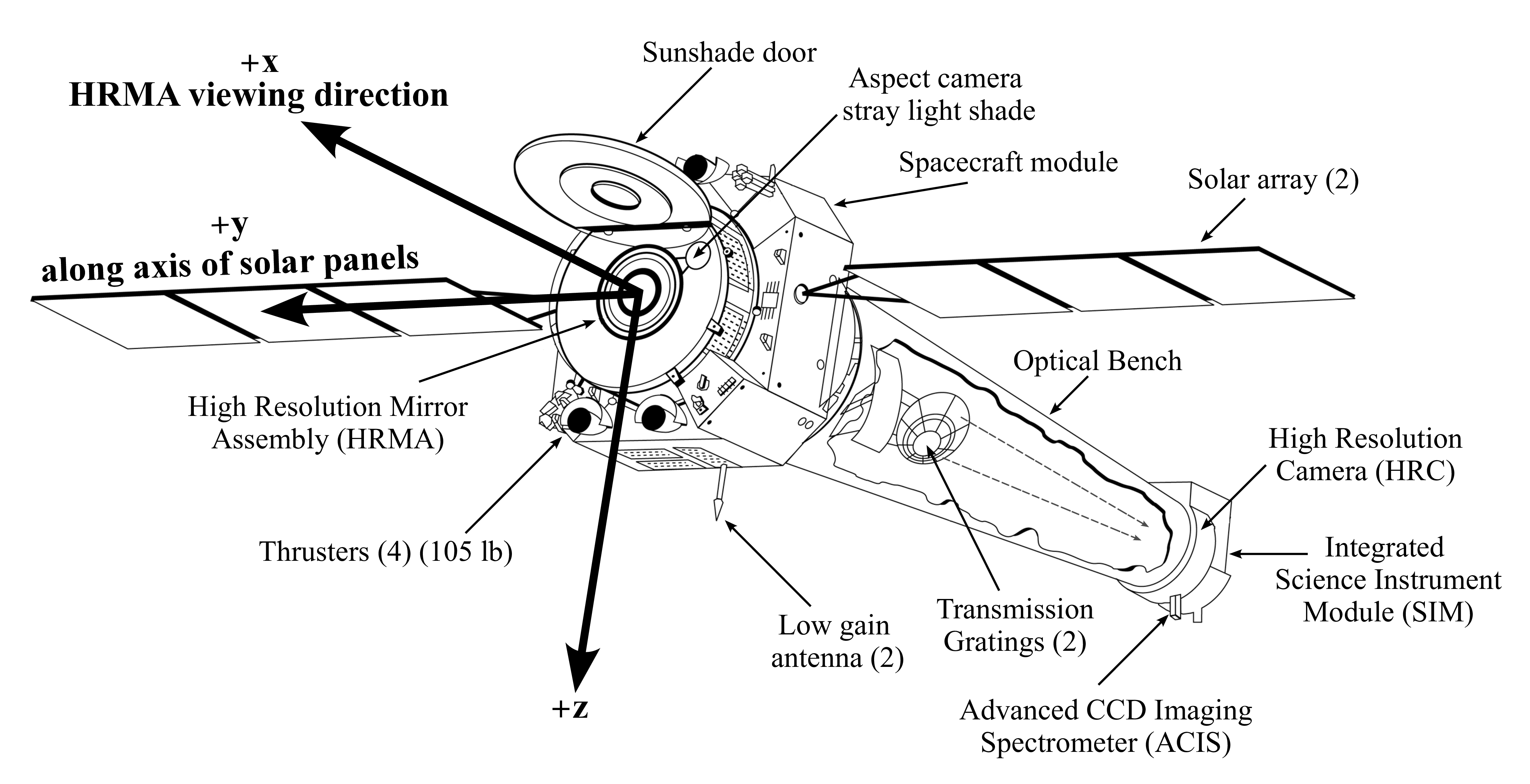 Figure 1.1: The Chandra Observatory with
certain subsystems labeled.
An outline drawing of the Chandra X-ray Observatory is shown in
Figure 1.1. Chandra consists of a spacecraft and a
telescope/science-instrument payload. The spacecraft provides power,
communications, command, data management, and pointing control and
aspect determination. The principal elements of the observatory that
will be discussed in this document are:
Figure 1.1: The Chandra Observatory with
certain subsystems labeled.
An outline drawing of the Chandra X-ray Observatory is shown in
Figure 1.1. Chandra consists of a spacecraft and a
telescope/science-instrument payload. The spacecraft provides power,
communications, command, data management, and pointing control and
aspect determination. The principal elements of the observatory that
will be discussed in this document are:
- The High Resolution Mirror Assembly (HRMA; Chapter 4)
- The Aspect System (Chapter 5)
- The Focal-plane Science Instruments (SIs):
- The Advanced CCD Imaging Spectrometer
(ACIS; Chapter 6)
- The High Resolution
Camera (HRC; Chapter 7)
- The Objective Transmission Gratings:
- High Energy Transmission Grating (HETG; Chapter 8)
- Low Energy Transmission Grating (LETG; Chapter 9)
These and related elements of the Chandra Project are introduced
briefly in the remainder of this chapter.
1.4 Pointing Control and Aspect Determination (PCAD)
The PCAD system
controls the pointing and dithering of the observatory and provides
the data from which both the relative and absolute aspect are
determined. Dithering is imposed to spread the instantaneous
image over many different pixels of the focal-plane detector to smooth
out pixel-to-pixel variations. The dither pattern is a Lissajous
figure (and can be seen quite clearly in the un-aspect corrected data
from bright point sources). The amplitude, phase, and velocity depend
on which instrument (ACIS or HRC) is in the focal plane.
Key elements of the PCAD system are the set of redundant gyroscopes,
momentum wheels, and an aspect camera assembly (ACA) consisting of a four inch
optical telescope with (redundant) CCD detector. The aspect camera
simultaneously images a fiducial light
pattern
produced by light emitting diodes placed around the focal-plane
instruments along with the flux from up to five bright stars that may
be in the aspect camera's field-of-view. An interesting consequence is
that the user may request that one of the targets of the aspect camera
be at the location of the X-ray target. For bright optical
counterparts, this option allows real-time optical monitoring, albeit
at the price of reducing the accuracy of the aspect solution-see
Chapter 5
for further details. This option will be implemented only pursuant to a feasibility analysis during the planning and scheduling process.
The HRMA
consists of a nested set of four
paraboloid-hyperboloid (Wolter-1) grazing-incidence X-ray mirror
pairs, with the largest having a diameter of 1.2 m (twice that of the
Einstein Observatory). The focal length is 10 m.
The mirror glass was obtained from Schott Glaswerke; grinding and
polishing was performed at Hughes Danbury Optical Systems; coating at
Optical Coating Laboratory; and the mirror alignment and mounting at
Eastman Kodak Co. The mirrors weigh about 1000 kg. Details of the
HRMA and its performance are presented in Chapter 4.
The Chandra Telescope Scientist was the late Dr. Leon Van Speybroeck of the
Smithsonian Astrophysical Observatory.
1.6 Science Instrument Module (SIM)
The Science Instrument Module
consists of the special hardware that provides mechanical
and thermal interfaces to the focal-plane scientific instruments
(SIs). The most critical functions from an observer's viewpoint are
the capability to adjust the telescope focal length and the ability to
move the instruments along an axis orthogonal to the optical axis.
The SIM houses the two focal instruments, the ACIS and the
HRC. Each of these have two principal components: ACIS-I and -S and HRC-I and -S, respectively. The focal-plane instrument layout is shown in Figure
1.2. The SIM moves in both the X-axis (focus) and
the Z-axis (instrument and aimpoint (1.6.1) selection). Note
that the Y-Axis parallels the dispersion direction of the gratings.
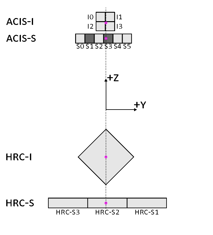 Figure 1.2: Arrangement of the ACIS and the HRC in the focal plane. The
view is along the axis of the telescope from the direction of the
mirrors. For reference, the two back-illuminated ACIS-S chips are
shaded. Numbers indicate positions of chips I0-I3 and S0-S5.
SIM motion can be used to place the aimpoint at any point
on the vertical dashed line denoting the spacecraft Z axis direction. Nominal detector aimpoints are indicated with small circles.
Aimpoints are the nominal positions on the detector where the flux
from a point source is placed. Note there is a slight (less than 20")
distinction between the aimpoint and the on-axis position, which for
most practical purposes can be ignored. The aimpoints are discussed in
detail in the chapters about each instrument and in
Chapters 4 and 5.
Figure 1.2: Arrangement of the ACIS and the HRC in the focal plane. The
view is along the axis of the telescope from the direction of the
mirrors. For reference, the two back-illuminated ACIS-S chips are
shaded. Numbers indicate positions of chips I0-I3 and S0-S5.
SIM motion can be used to place the aimpoint at any point
on the vertical dashed line denoting the spacecraft Z axis direction. Nominal detector aimpoints are indicated with small circles.
Aimpoints are the nominal positions on the detector where the flux
from a point source is placed. Note there is a slight (less than 20")
distinction between the aimpoint and the on-axis position, which for
most practical purposes can be ignored. The aimpoints are discussed in
detail in the chapters about each instrument and in
Chapters 4 and 5.
1.7 Ground System
The ground system consists of the CXC in Cambridge, Massachusetts, the OCC in
Burlington, Massachusetts, the
Engineering Support Center
(ESC) at
MSFC, and various NASA communications systems including the Deep
Space Network operated for NASA by the Jet Propulsion Laboratory (JPL). See
Section 2.6.2 for details.
The Chandra orbit is highly elliptical and varies with time. In 2023-July the perigee altitude, after decreasing since late 2017, reached its mission minimum of 1045 km; the apogee height, after rising since 2017, reached a maximum of ∼ 148,000 km. The orbital eccentricity accordingly reached its maximum of ∼ 0.91 in 2023-July. Since then, the eccentricity has decreased, reaching ∼ 0.84 in mid-2025, at which time the apogee altitude was ∼ 142,000 km and the perigee altitude ∼ 6680 km. The trend for decreasing eccentricity and increasing perigee altitude will continue until ∼ 2029. The orbit allows for high observing efficiency as the satellite spends most of the time well above the radiation belts ( ∼ 70%) and long observations (currently ∼ 180 ksec) are made possible in principle by the orbital period of 63.5h (but see Section 3.3 for limitations due to spacecraft thermal considerations).
1.9 Particle Detector
There is a particle detector
mounted near
the telescope, called the Electron, Proton, Helium INstrument (EPHIN; see Section 2.5). This detector was used to monitor the local
charged particle environment as part of the scheme to protect the
focal-plane instruments from particle radiation damage; owing to
performance degradation and erratic behavior, EPHIN is no longer used in
this protective function as of 2013-Nov and was depowered in 2018-Sep.
The Co-Principal Investigators of the EPHIN instrument are
Drs. Reinhold Muller-Mellin and Hoarst Kunow of the University of
Kiel, Germany.
The ACIS is composed of two CCD arrays: a 4-chip array, ACIS-I, and a
6-chip array, ACIS-S. The CCDs are flat, but the chips in each array
are positioned (tilted) to approximate the relevant focal surface:
that of the HRMA for ACIS-I and that of the HETG Rowland circle for
ACIS-S. ACIS-I was designed for CCD imaging and spectrometry;
ACIS-S can be used both for CCD imaging spectrometry and also for
high-resolution spectroscopy in conjunction with the HETG grating.
There are two types of CCD chips. ACIS-I is composed of
front-illuminated (FI) CCDs. ACIS-S is composed of 4 FI and 2
back-illuminated (BI) CCDs. The BI S3 chip is at the best focus position and is normally
used for ACIS-S imaging observations. ACIS-I is better when wider
field (16 arcmin × 16 arcmin) and/or higher energy response is needed; ACIS-S imaging is better when low energy response is preferred and a smaller
(8 arcmin × 8 arcmin) field of view is sufficient.
The efficiency of the ACIS instrument has
been discovered to be slowly changing with time, most likely as a result
of molecular contamination build-up on the optical blocking filter.
The BI CCDs response extends to lower energies
than the FI CCDs and the energy resolution is mostly independent of
position. The low-energy response of the BI CCDs is partially compromised
by the contaminant build-up. The FI CCD response is more efficient
at higher energies, but the energy resolution varies with position due
to radiation damage caused by protons reflecting through the telescope
during radiation-zone passages in the early part of the
mission. Details on the ACIS are given in Chapter 6.
The Principal Investigator is Prof. Gordon Garmire of the Huntingdon Institute for X-ray Astronomy, LLC.
The HRC
is composed of two microchannel plate (MCP)
imaging detectors: the HRC-I, designed for wide-field imaging, and
the HRC-S, designed to serve as a read-out for the LETG. The HRC-I is
placed at right angles to the optical axis, tangent to the focal
surface. The HRC-S is made of three flat elements, the outer two of
which are tilted to approximate the LETG Rowland circle. The
HRC detectors have the highest spatial resolution on Chandra,
matching the HRMA point spread function most closely. Under certain
circumstances, the HRC-S detector also offers the fastest time
resolution (16 μs). Details concerning the HRC are in
Chapter 7.
The current Instrument Principal Investigator is Dr. Ralph Kraft of the
Smithsonian Astrophysical Observatory, who was appointed to this
position following the untimely passing in 2015-Aug of the original
HRC Principal Investigator, Dr. Stephen Murray of SAO.
The HETG
, when operated with the ACIS-S,
forms the High-Energy Transmission Grating Spectrometer (HETGS) for
high resolution spectroscopy. The
HETGS achieves resolving power (E/∆E) up to 1000 in the band
between 0.4 keV and 10.0 keV. The HETG is composed of two grating
assemblies-the High Energy Grating (HEG) and the Medium Energy
Grating (MEG)-on a single structure that can, by command, be
placed in the optical path just behind the HRMA. The HEG intercepts
X-rays from only the two inner mirror shells and the MEG intercepts
X-rays from only the two outer mirror shells. The HEG and
MEG dispersion directions are offset by 10 deg so the two
patterns can be easily distinguished. Details are presented in
Chapter 8.
The original Instrument Principal Investigator was Prof. Claude
Canizares (retired), and the current Principal Investigator is
Dr. Herman Marshall of the MIT Kavli Institute for Astrophysics and Space Research.
The LETG
, when operated with the HRC-S, forms the Low
Energy Transmission Grating Spectrometer (LETGS). The
LETGS provides the highest spectral resolution on Chandra at low
(0.08-0.2 keV) energies. The LETG is composed of a single grating
assembly that, on command, can be placed in the optical path behind
the HRMA. The LETG grating facets intercept and disperse the flux
from all of the HRMA mirror shells. Details are given in
Chapter 9.
The LETG was developed at the Laboratory for Space Research
in Utrecht, the Netherlands, in collaboration with the
Max-Planck-Institut für Extraterrestrische Physik in Garching,
Germany. The original Instrument Principal Investigator was Dr. Albert Brinkman (retired), who was succeeded as PI by Dr. Jelle Kaastra (retired) and then by Dr. Liyi Gu, all of the Laboratory for Space Research.
1.14 Effective Area Comparisons
The effective areas of the imaging instruments are shown in
Figure 1.3. The ACIS curves allow for the expected
degradation of the ACIS efficiency caused by molecular contamination
predicted for the middle of Cycle 28. A comparison of the
effective areas of the grating spectrometers are shown in
Figure 1.4. Note that the data from the HEG and
MEG are obtained simultaneously. The comparisons shown here are
based on the most recent calibration at the time of issuance of this
document and are subject to revision. The proposer is urged to read
the detailed material in the appropriate chapters and examine the
CXC web site (see Section 1.16) for updates.
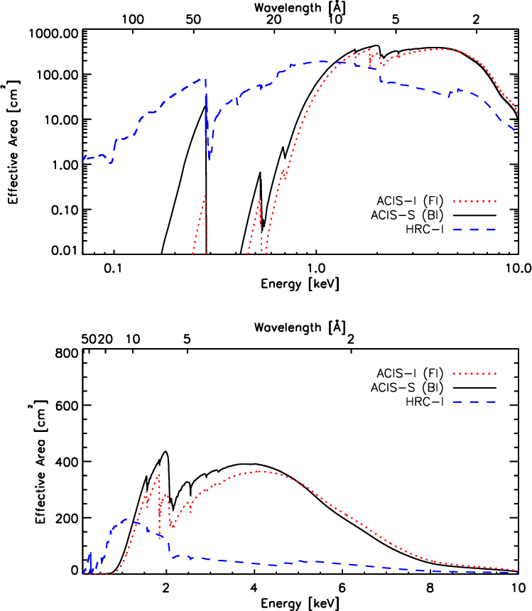 Figure 1.3: Comparison of the on-axis effective areas for observing
a point source (integrated over the PSF) of the HRMA /HRC-I, the
HRMA/ACIS(FI), and the HRMA/ACIS(BI) combinations. The
ACIS curves show the predicted values for the middle of Cycle 28.
Figure 1.3: Comparison of the on-axis effective areas for observing
a point source (integrated over the PSF) of the HRMA /HRC-I, the
HRMA/ACIS(FI), and the HRMA/ACIS(BI) combinations. The
ACIS curves show the predicted values for the middle of Cycle 28.
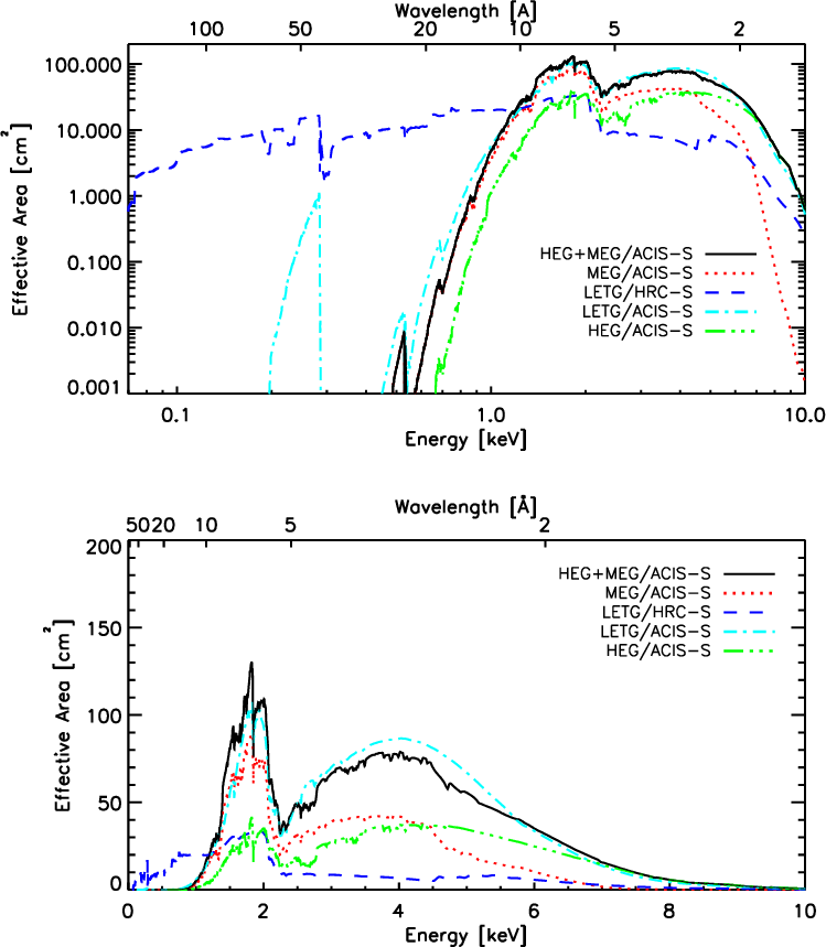 Figure 1.4: Comparison of the total first-order (positive and negative
orders combined) effective areas of the LETG and HETG (HEG and MEG are
shown separately and summed) spectrometers. HEG and MEG spectra are
obtained simultaneously and can sometimes be usefully combined. For a
given energy in the range of overlap, the resolving power of the HEG is
approximately twice that of the MEG, which in turn is approximately
twice that of the LETG. The LETG extends to much lower energies than
reached by the HETG+ACIS-S combination, especially when used with the
HRC-S detector. For full details on spectrometer performance and
observation planning see Chapters 8 (HETG) and
9 (LETG).
Figure 1.4: Comparison of the total first-order (positive and negative
orders combined) effective areas of the LETG and HETG (HEG and MEG are
shown separately and summed) spectrometers. HEG and MEG spectra are
obtained simultaneously and can sometimes be usefully combined. For a
given energy in the range of overlap, the resolving power of the HEG is
approximately twice that of the MEG, which in turn is approximately
twice that of the LETG. The LETG extends to much lower energies than
reached by the HETG+ACIS-S combination, especially when used with the
HRC-S detector. For full details on spectrometer performance and
observation planning see Chapters 8 (HETG) and
9 (LETG).
1.15 Allocation of Observing Time
Observing time is awarded through the NASA proposal and peer
review process. The prospective
user must submit a proposal in which the observation is described
and justified in terms of the expected results.
The proposer must also show that the observation is well suited to
Chandra and that it is technically feasible. Refer to the Call for
Proposals (CfP,
https://cxc.harvard.edu/proposer/CfP/)
for more information.
1.16 How to Get Information and Help
The CXC web page
(https://cxc.harvard.edu)
provides access to documents, proposal preparation tools, and
proposal submission software.