

Creating Higher-order Responses for HRC-S/LETG Spectra
[CIAO 3.4 Science Threads]
OverviewLast Update: 1 Dec 2006 - reviewed for CIAO 3.4: no changes Synopsis: Because of the low energy resolution in the HRC-S, the PHA2 file contains only two rows (negative and positive) containing all the spectral orders. While it is not possible to separate the overlapping orders, CIAO can make response files (gRMFs and gARFs) for higher orders (m up to 10), allowing you to model them in Sherpa. Deciding how many orders to include may not be simple. The best advice is to use the empirical approach, and keep adding one or two orders at a time to your analysis until variations in fit results reach the level of other uncertainties. If nothing else, this will provide an enhanced appreciation for the level of systematic uncertainties in your analysis. This is also a good approach to use because the computational load on Sherpa steadily increases as orders are added. Purpose: This thread describes how to estimate the importance of higher orders when analyzing LETG/HRC-S spectra, so that one can at least determine the minimum number of orders with which to start. Keep in mind that the spectrum of order m has m times the dispersion of 1st order, i.e., continuum is more spread out in terms of mm/Å on the detector. Likewise, resolved lines will become broader (in mm) as the order increases. |
Contents
Explanation
The number of counts at the single detector position mλ is equal to the sum of counts from 1st order (at emitted wavelength λ), 2nd order (at λ/2), 3rd order (λ/3), etc. This can be written as
= Σmf(λ/m)Am(λ/m)
where I is the intensity (counts/s/Å) observed at a given location on the detector, f is the source flux (photons/s/cm^2/Å) at a specific wavelength, and Am is the LETG/HRC-S effective area (cm^2) for order m at that wavelength.
This can be rewritten for integrated line intensities (in cts/s) as
= ΣmL(λ/m) [Am(λ/m)/A1(λ)]
and for continuum (cts/s/Å) as
= Σm(1/m)C(λ/m)[Am(λ/m)/A1(λ)].
(Recall that the extra 1/m factor for the continuum equation is because continuum intensity is measured per unit wavelength, and the dispersion of higher-order spectra is proportional to m. Line intensities are integrated, so broadening doesn't matter for them.)
In the above equations, the only directly measured intensity is L(mλ) or C(mλ), but as long as most of the counts at a given mλ come from 1st order, one can estimate the contribution of each order in the mλ spectrum, as shown in the examples. The effective areas, Am, can be read from these plots.

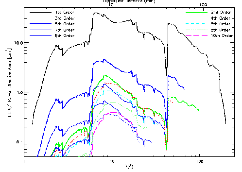
Note that the two plots contain the same information, but present it differently: mλ vs λ for the x-axis.
At any wavelength, the combined effective area of orders beyond m=10 is at most a few percent of the 1st order EA unless nearly all of the source's emission is between 6 and 17 Å, in which case the observer would almost certainly want to use the HETG with ACIS-S.
Example Analyses
Continuum
Here we use ObsId 460 (LETG/HRC-S, 3C 273) to illustrate
the steps. This plot of the
positive-order spectrum ![]() has the wavelengths we
will focus on marked with a red "X".
has the wavelengths we
will focus on marked with a red "X".
-
3rd order often provides the strongest higher-order contamination, so we begin with that, looking at mλ = 90 Å, which has contributions from 1st order (90 Å), 2nd order (45 Å), 3rd order (30 Å), etc.
-
The 3rd order contribution is approximately equal to (1/3)C(λ/3)[A3(λ/3)/A1(λ)]. There are about 4 counts/bin at 90 Å (C(λ) and 60 at 30 Å (C(λ/3). From the effective area plots, A1(90 Å) = 8 cm^2 and A3(30 Å) = 1.1 cm^2, so 3rd order contributes (1/3)(60 counts)(1.1cm^2/8cm^2) = 2.8 of the total of 4 counts/bin.
-
Similarly, the number of counts/bin from other orders is:
2nd: (1/2)(60 counts at 45.0 Å)(0.8cm^2/8cm^2) = 3.0
4th: (1/4)(70 counts at 22.5 Å)(0.5cm^2/8cm^2) = 1.1
5th: (1/5)(100 counts at 18.0 Å)(0.5cm^2/8cm^2) = 1.2
6th: (1/6)(120 counts at 15.0 Å)(0.7cm^2/8cm^2) = 1.8
7th: (1/7)(120 counts at 12.9 Å)(0.3cm^2/8cm^2) = 0.6
8th: (1/8)(120 counts at 11.2 Å)(0.6cm^2/8cm^2) = 1.1
9th: (1/9)(130 counts at 10.0 Å)(0.35cm^2/8cm^2) = 0.6
10th: (1/10)(150 counts at 9.0 Å)(0.35cm^2/8cm^2) = 0.7
In this case, orders 2-10 contribute an estimated total of more than 12 counts/bin. The fact that this is higher than the observed total of 4 counts/bin simply means that higher orders are also important at shorter wavelengths, thus inflating the apparent spectral intensity at λ/m and leading to overestimates of higher-order contributions at λ. In this extreme example, higher orders contribute virtually all the flux at long wavelengths (beyond roughly 70 Å), and spectral fitting at those wavelengths will be of dubious quality.
Line Spectrum
For this example we refer to the coronal line spectrum of Capella, as shown in Figure 9.25 of the POG (from Brinkman et al. 2000, ApJ, 530, L111).
-
Say we want to analyze the region around 45 Å, which may contain 2nd order features from 22 Å, 3rd order from 15 Å, etc. There is a strong line at 15.02 Å so we focus on 3rd order.
-
The 3rd order contribution is approximately equal to L(15.02 Å)[A3(15.02 Å)/A1(45.06 Å)]. From Brinkman et al., the intensity of the 15.02 Å line is 44.2 cts/ks. From the effective area plots, A1(45 Å) = 25 cm^2 and A3(15 Å) = 2.5 cm^2, so the 3rd order line at mλ should have an intensity of (44.2 cts/ks)(2.5cm^2/25cm^2) = 4.4 cts/ks. Indeed, Brinkman et al. measure 4.2 cts/ks, which is nearly as large as the 1st order intensity of the Si XII line at 44.16 Å.
-
Similarly, 5th order of the 9.169 Å Mg XI line will appear at 45.84 Å with (6.2 cts/ks)(1.2cm^2/25cm^2) = 0.3 cts/ks, probably blending with the 1.9-cts/ksec Si XII line at 45.68 Å. the Si XII line at 44.16 Å.
-
The Si XIII line at 6.648 Å is the shortest wavelength feature of any significance, and it would appear in 7th order at 46.54 Å with (5.1 cts/ks)(0.35cm^2/25cm^2) = 0.07 cts/ks, which is small but perhaps non-negligible depending on the analysis goals.
Related Threads
The following threads show how to create response files for HRC-S/LETG data:
History
| 10 May 2005 | original version, new for CIAO 3.2 |
| 06 Dec 2005 | reviewed for CIAO 3.3: no changes |
| 02 Nov 2006 | added note about orders beyond m=10 in Explanation section |
| 01 Dec 2006 | reviewed for CIAO 3.4: no changes |