Chandra Calibration Status Summary

as of July 2017

Detector/GratingCalibration ProductAverage UncertaintyCommentsAdditional Information
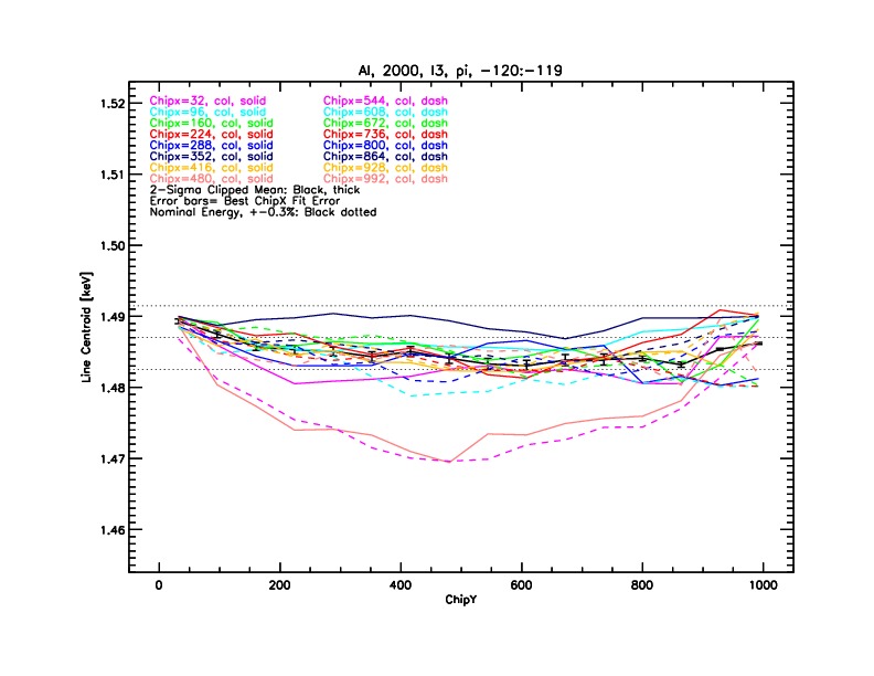
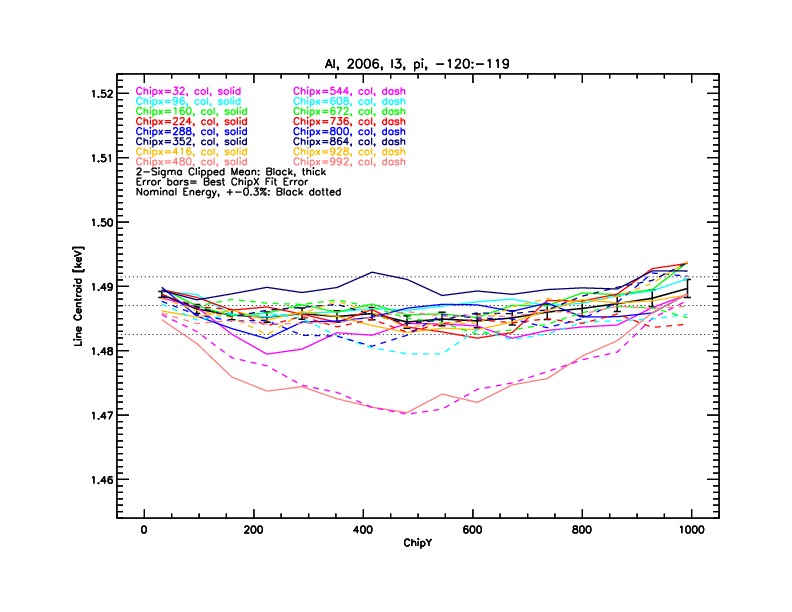
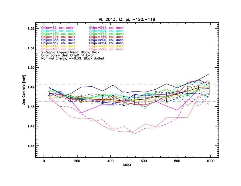
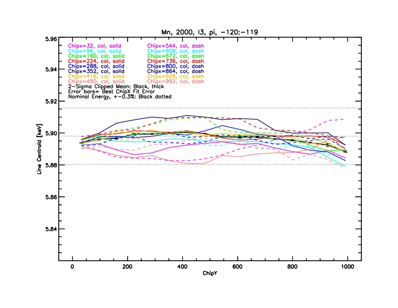
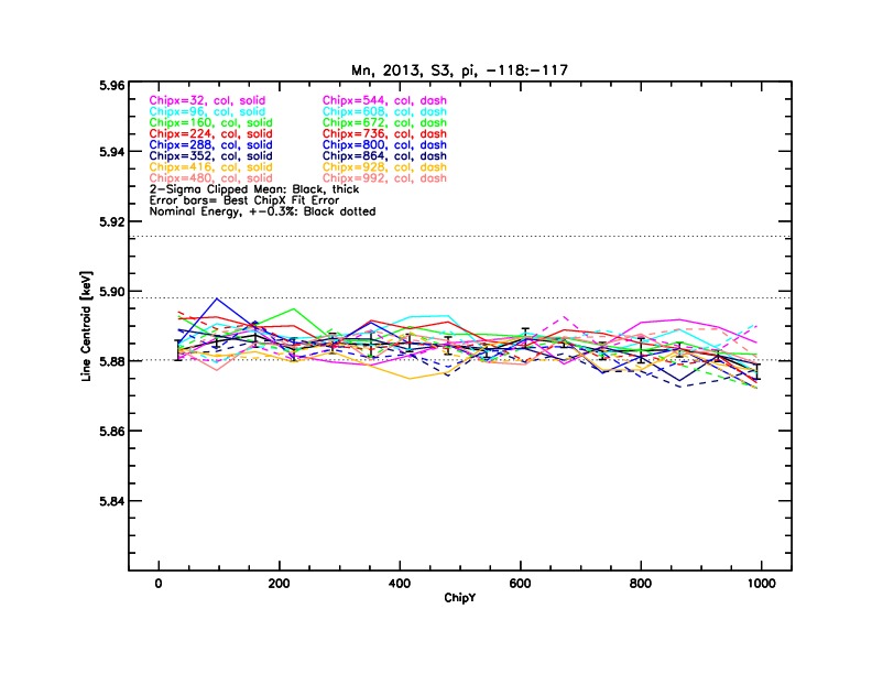
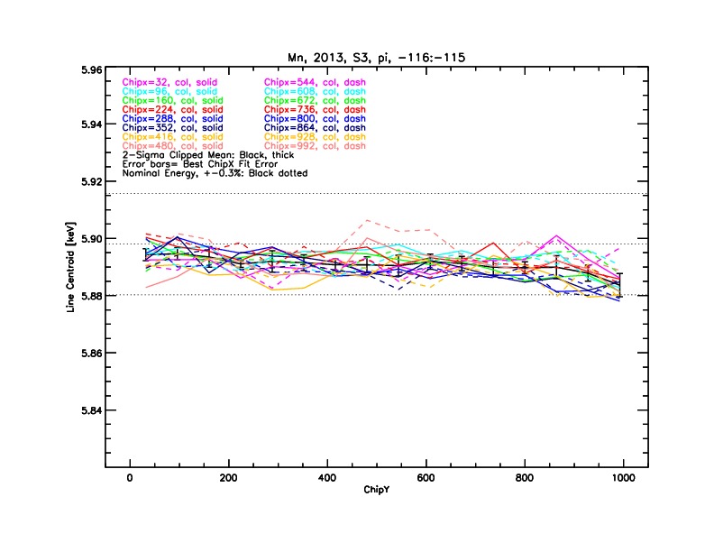
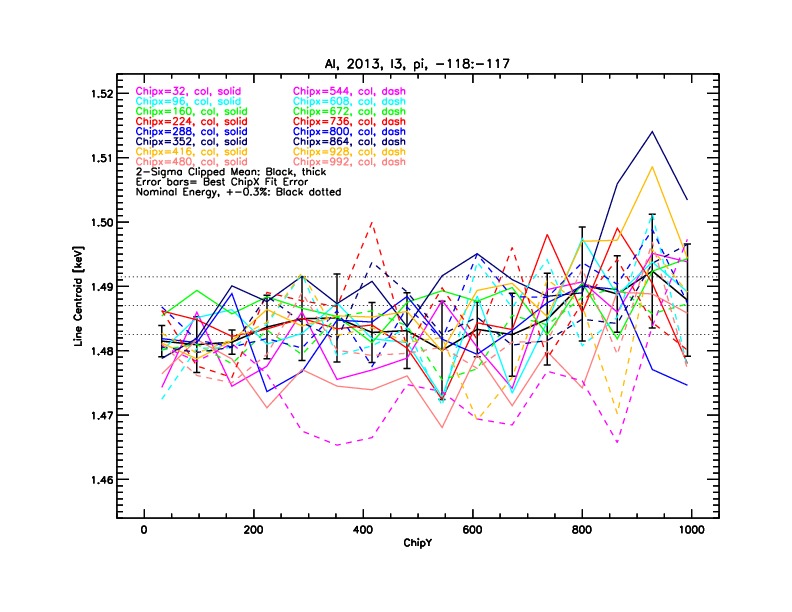
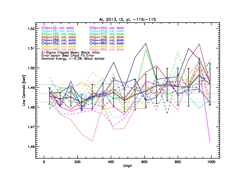
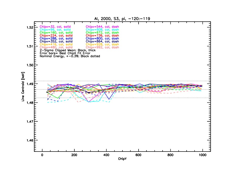
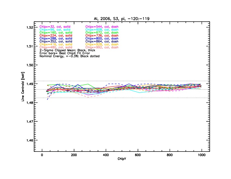
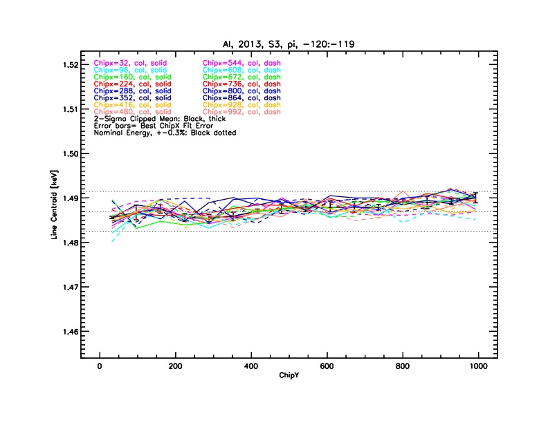
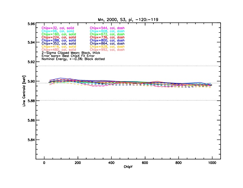
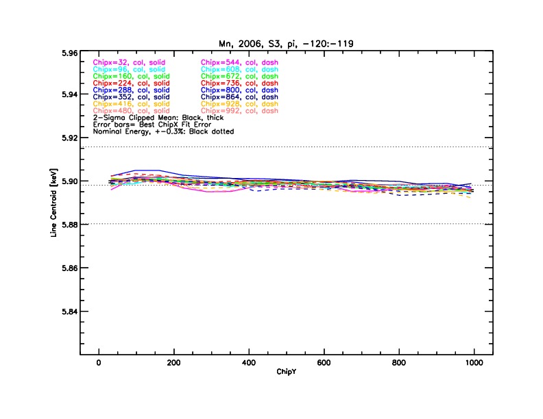
ACISDector Gain0.3% The ACIS gain is calibrated with the ACIS external calibration source (ECS), which consists of three 55Fe sources that produce L-shell emission lines of Fe (0.71 keV) and Mn (0.64 keV) and K-shell emission lines of Al (1.49 keV), Ti (4.5 keV), and Mn (5.9 keV). ACIS is exposed to the ECS whenever it is in the stowed position (i.e., when Chandra passes through the radiation belts). Prior to Feb. 2016, updated ACIS gain tables were released quarterly by co-adding three month of ECS data binned in 32 by 32 pixel regions. The half-life of 55Fe is only 2.7 years, so it has recently become necessary to co-add six months of ECS data to achieve sufficient photon statistics to calibrate the gain. Since Feb. 2016, updated ACIS gain tables are released semi-annually. Caveats:
  • In general, the uncertainty in detector gain depends on the date of the observation (due to radiation damage and the resulting increase in CTI), type of CCD (BI or FI), position (chipx, chipy) on the CCD and the focal plane temperature at the time of the observation.

  • The gain on the BI chips has been more stable over the course of the mission compared to the FI chips due to the smaller relative increase in CTI (i.e., the CTI on the BI chips was greater at launch).

  • For the BI chips, the uncertainty in the detector gain remains less than 0.3% even for warmer focal plane temperatures.

  • For the FI chips, the uncertainty in the detector gain can approach 0.6% at high rows (chipy) and warm focal plane temperatures.

Web Pages

Papers/Memos

Presentations/Plots

ACISSpectral Resolution30 eV The quoted uncertainty in the spectral resolution of the ACIS detectors was estimated by fitting a large sample of ECS data and corresponds to the typical FWHM a user would obtain when fitting a Gaussian profile to an emission line with zero intrinsic width (i.e., the current version of the ACIS response matrix under estimates line broadening due to the effects of CTI and variations in the focal plane temperature). Caveats:
  • In general, the uncertainties in the ACIS spectral resolution have all of the same dependencies as the detector gain listed above.

  • Over the course of the mission, the uncertainty in the spectral resolution of the BI chips has increased from 5 to 30 eV at 1 keV and from 20 to 60 eV at 6 keV.

  • For the BI chips, the uncertainty in the spectral resolution is nearly independent of chipy.

  • The FI chips show a more pronounced degradation in spectral resolution with increasing chipy with uncertainties at 1 keV increasing from 20 eV near the read-out (low chipy ) up to 40 eV at the top of the chip (large chipy).

Web Pages

Presentations/Plots

ACISEffective Area4% The quoted uncertainty in the ACIS effective area corresponds to the rms scatter in broad band fluxes for a sample of steady calibration sources (e.g., supernova remnants and clusters of galaxies) that have been periodically observed with ACIS over the course of the mission and thus represents the uncertainty in the relative effective area of the ACIS detectors. The uncertainty in the absolute ACIS effective area is a more difficult problem and can best be accessed through cross-calibration studies with other X-ray missions such as those completed by the International Astronomical Consortium for High Energy Astrophysics (IACHEC). Caveats:
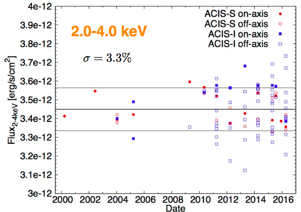
  • The attached plots show the scatter in flux measurements within several energy bands for all Abell 1795 observations through 2016. These observations were taken with both ACIS-I and ACIS-S, at many different locations on the detectors, and at many times over the course of the mission. The observed scatter in these plots is the best estimate of the systematic uncertainty in the relative ACIS effective area. The quoted uncertainty of 4% strickly refers to the 0.5-7.0 keV bandpass. The attached plots show that there is some variation with energy band.
  • The main factor governing the uncertainty in the ACIS effective area below 2 keV is the continual build-up of contamination onto the ACIS filters. The calibration team has developed a high fidelity contamination model which estimates the transmission of the contaminant as a function of energy, position on the detector, and date of the observation.

  • Both FI and BI chips suffer from a steady loss in QE at all energies due to continued radiation damage and the subsequent increase in CTI. The average QE loss has been about 0.2% per year for the BI chips and about 0.1% per year for the BI chips. This reduction in detector QE is accounted for in default CIAO processing and leads to a negligible increase in the uncertainty in the ACIS effective area.

  • All Chandra observations are consistent with no degradation in the effective area of the High Resolution Mirror Assembly (HRMA) over the course of the mission.

Web Pages

Papers/Memos

Presentations/Plots

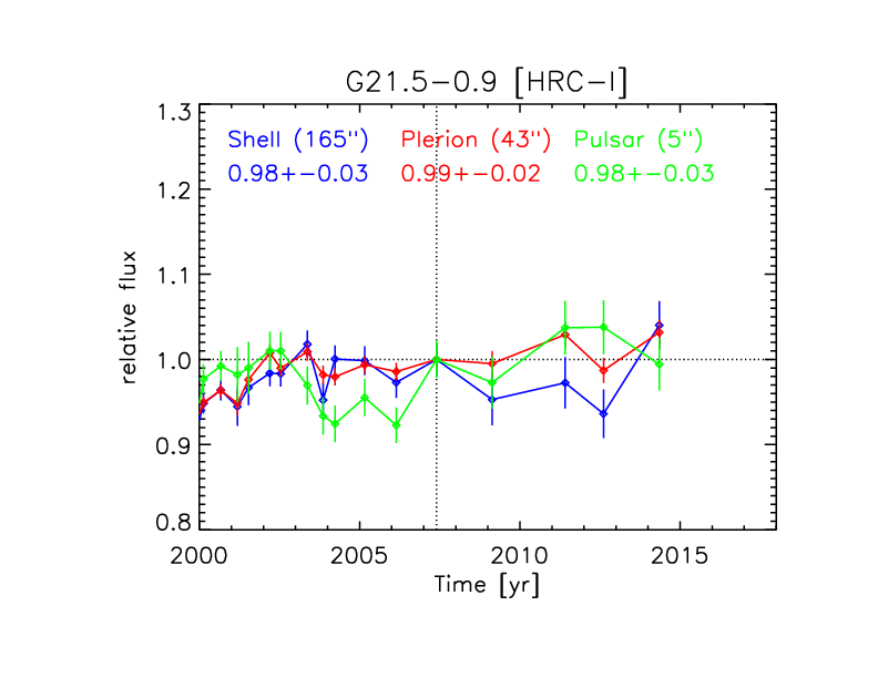
HRCEffective Area5% The effective area of the HRC-I and HRC-S has been monitored throughout the Chandra mission with periodic observations of steady sources (mostly the white dwarf HZ43 and the supernova remnant G21.5-09). The rms scatter in the computed fluxes of these two sources in HRC-I and HRC-S observations over the course of the mission is approximately 5%. Caveats:
  • Early in the mission (1999-2002), the HRC-I and HRC-S fluxes for G21.5-09 differed by about 10%. since that time, the scatter in derived derived fluxes has remained consistent at approximately 3%.

  • The gain and QE of the HRC-I and HRC-S have both slowly but steadily declined since launch. Since 2012, the HRC-I count rate for the soft source HZ43 has declined by about 5%, while the HRC-I count rate for the harder source G21.5-09 has remained stable. The gain and QE loss for the HRC-S is discussed more extensively in the LETG/HRC-S section below.

Web Pages

Papers/Memos

Presentations/Plots

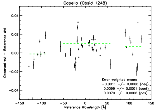
LETGAbsolute Wavelength Scale0.01 Å The quoted uncertainty in absolute wavelength corresponds to the rms scatter in the difference between lab wavelengths and derived wavelengths for emission lines detected in a LETG/HRC-S observation of Capella. The derived uncertainty includes emission lines detected over the full wavelength range covered by the HRC-S. Caveats:
  • There are some trends in the accuracy of the absolute wavelength calibration with distance along the dispersion axis. The rms scatter between lab wavelengths and derived wavelengths is slightly less on the central HRC-S plate (λ < 60 Å) compared to the outer HRC-S plates.

Web Pages

Papers/Memos

Presentations/Plots

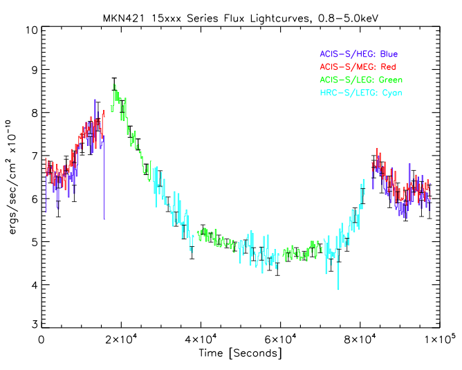
LETGEffective Area8% To maintain a stable LETG/HRC-S and LETG/ACIS-S effective area calibration, the CXC calibration team carries out yearly LETG/HRC-S observations of the white dwarf HZ43 and yearly LETG/ACIS-S observations of the isolated neutron star RXJ 1856, both of which are stable, soft sources. Since all bright, hard X-ray point sources are variable, a set of interleaved observations are completed each year which cycle through all grating/detector combinations while Chandra observes the same target. In most cases, the target has been the blazar Mkn 421. These observations are then used to cross-calibrate between the different grating/detector combinations. Over a broad wavelength range, the uncertainty in the relative effective areas of all grating/detector combinations is less than 8%. Due to the steady decline in the gain and QE of the HRC-S during the course of the Chandra mission, the high voltage of the HRC-S was increased in Mar 2012 to restore the gain and QE to near launch values. The loss in HRC-S gain and QE is corrected with the annual release of updated QE and gain files. These updated files are used during default CIAO processing. Caveats:
  • The uncertainty in the relative LETG/HRC-S effective area decreases from 8% below 1 keV to about 5% above 3 keV.

Web Pages

Papers/Memos

Presentations/Plots

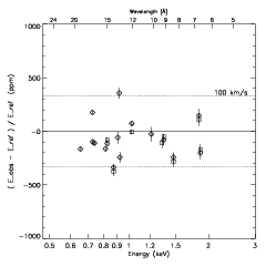
HETGAbsolute Wavelength Scaleδ λ ⁄ λ = 10-5 The absolute wavelength scale of HETG/ACIS-S grating data has been primarily calibrated with observations of the emission line source Capella. No time-dependent effects have been measured over the course of the mission.

Web Pages

Papers/Memos

Presentations/Plots

HETGEffective Area8% All grating/detector effective areas, including the HETG/ACIS-S, are monitored with a set of yearly interleaved observations of the blazar Mkn 421. These observations are discussed in the LETG section above. Over a broad wavelength range, the uncertainty in the relative effective areas of all grating/detector combinations is less than 8%. In the left hand column is a link to a fluxed light curve for Mkn 421 during one of these interleaved observations. Even though Mkn 421 varies in brightness during the observation, the derived fluxes are in good agreement during the transitions between the different grating/detector combinations.

Web Pages

Papers/Memos

Presentations/Plots


ACIS-S3 Gain vs. Time

Line Energy200020062013
Al-Ka (1.49 keV)
Mn-Ka (5.9 keV)
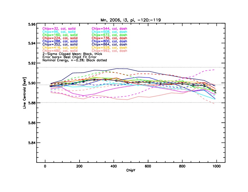
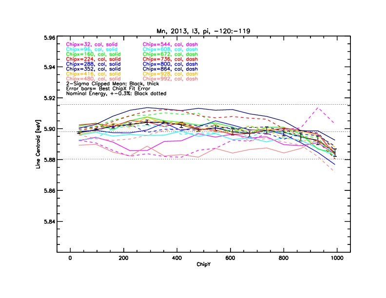
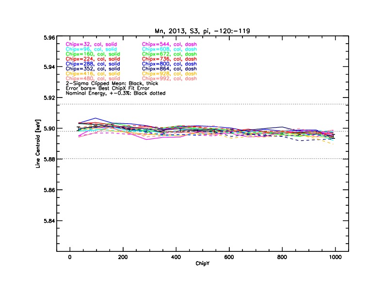
Derived photon energies for the ECS Al-Ka and Mn-Ka emission lines data at three epochs during the course of the Chandra mission. Each curve shows the derived energy for a given chipx along the full range of chipy. The horizontal lines show the lab measured line energies and +-0.3% limits about the line energy.

ACIS-I3 Gain vs. Time

Line Energy200020062013
Al-Ka (1.49 keV)
Mn-Ka (5.9 keV)
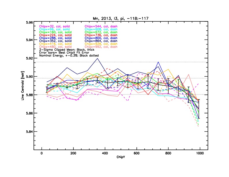
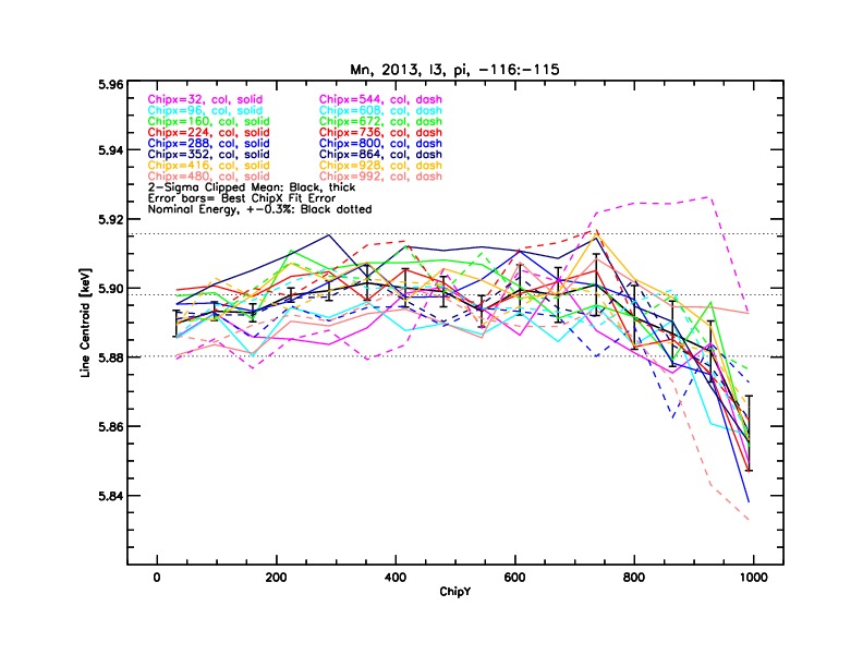
Derived photon energies for the ECS Al-Ka and Mn-Ka emission lines data at three epochs during the course of the Chandra mission. Each curve shows the derived energy for a given chipx along the full range of chipy. The horizontal lines show the lab measured line energies and +-0.3% limits about the line energy.

ACIS-S3 Gain vs. FP Temp (2013)

Line Energy-119.5 C-117.5 C-115.5 C
Al-Ka (1.49 keV)
Mn-Ka (5.9 keV)
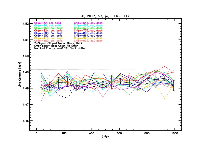
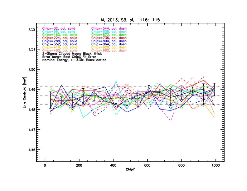
Derived photon energies for the ECS Al-Ka and Mn-Ka emission lines data at three different focal plan temperatures. Each curve shows the derived energy for a given chipx along the full range of chipy. The horizontal lines show the lab measured line energies and +-0.3% limits about the line energy.

ACIS-I3 Gain vs. FP Temp (2013)

Line Energy-119.5 C-117 C-115 C
Al-Ka (1.49 keV)
Mn-Ka (5.9 keV)
Derived photon energies for the ECS Al-Ka and Mn-Ka emission lines data at three different focal plan temperatures. Each curve shows the derived energy for a given chipx along the full range of chipy. The horizontal lines show the lab measured line energies and +-0.3% limits about the line energy.

ACIS-S3 FWHM

Line Energy-119.5117.5115.5
Al-Ka (1.49 keV)
Mn-Ka (5.9 keV)
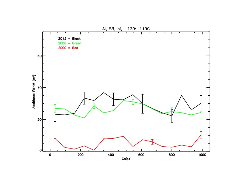
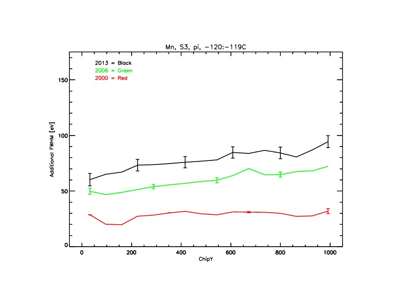
Additional broadening in the FWHM for Al-Ka and Mn-Ka emission lines at three different focal plan temperatures. Each plot shows the additional broadening in the FWHM at three different epochs during the course of the Chandra mission.

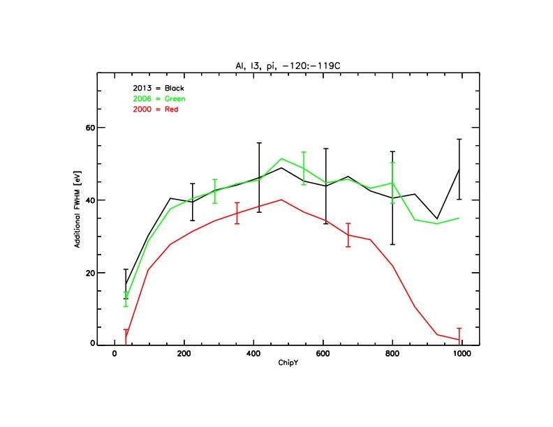
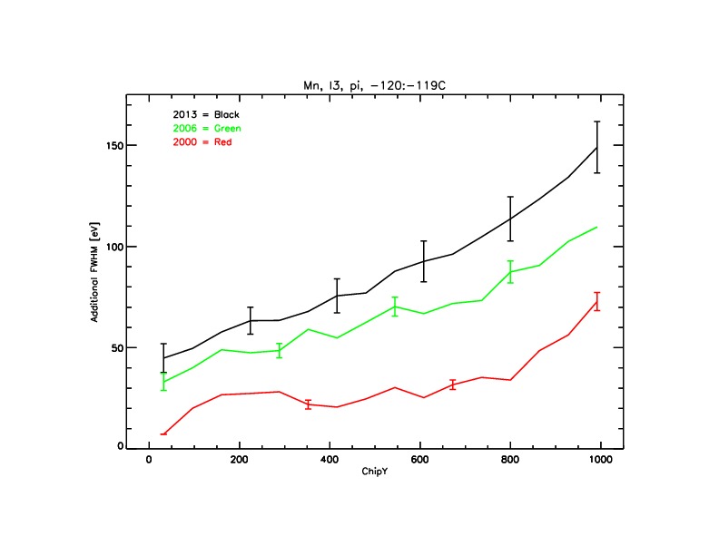
ACIS-I3 FWHM

Line Energy-119.5117.5115.5
Al-Ka (1.49 keV)
Mn-Ka (5.9 keV)
Additional broadening in the FWHM for Al-Ka and Mn-Ka emission lines at three different focal plan temperatures. Each plot shows the additional broadening in the FWHM at three different epochs during the course of the Chandra mission.

ACIS Effective Area - Abell 1795

Flux measurements in four different energy bands for all Abell 1795 observations through 2016. The heavy horizontal lines show the average flux in each plot. The dashed indicate the rms scatter in the flux measurements, which is also shown in the plots.

HRC Effective Area

Left-Derived HRC-I flux measurements (normalized to unity) within three regions of the G21.5-09 supernova remnant over the course of the Chandra mission. The mean and rms scatter for each region is given in the figure. Right-Ratio of counts to the adopted HZ43 spectral model for HRC-I (0th order), HRC-S (0th order), and HRC-S (1st order) observations taken over the course of the mission. Flux measurements in four different energy bands for all Abell 1795 observations through 2016. The heavy horizontal lines show the average flux in each plot. The dashed indicate the rms scatter in the flux measurements, which is also shown in the plots.

LETG Absolute Energies

Difference between the computed line wavelength and the laboratory line wavelength in a LETG/HRC-S spectrum of Capella. The mean and rms scatter for each of the three plates is given in the figure.

Interleaved Gratings Observations

Fluxed light cuve for Mkn 421 during a 90 ksec observation. The observation is bookended by HETG/ACIS-S observations. Between these observations, the LETG is inserted behind the mirrors, and the focal plane detector is cycled between the HRC-S and ACIS-S. This plot shows that even though the flux of Mkn 421 varies throughout the observation, the flux changes smoothly between the various detector/grating combinations.

HETG Absolute Energies

Difference between the computed line wavelength and the laboratory line wavelength in a HETG/HRC-S spectrum of Capella.