 |
| Test | Energy (keV) | XRCF EER | MARX EER |
| H-IAI-PI-1.021 | 6.4 | 2.75 | 2.00 |
| H-IAI-CR-1.001 | 1.486 | 2.39 | 2.12 |
| H-IAI-PI-3.001 | 1.486 | 3.15 | 2.12 |
 |
Any comparison between model and measurement data is subject to uncertainties in our knowledge of the state of the telescope, most importantly the location of ACIS along the x (defocus) axis. ACIS was shutter focussed at Al-Ka following the pump-down period when the telescope became thermally stable. The focus precision was limited by our ability to measure the relative centroids of the X-ray spot images formed by the HRMA quadrant shutters. Additional focus errors may have accrued by detector drift and by the repeated movement of the five axis mount. The real focus location is not particularly well defined, and this uncertainty must be kept in mind when comparing the data to models.
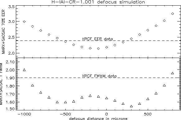
Our analysis of the PRF core relies heavily on the Al-Ka test H-IAI-CR-1.001, as this is the test with lowest X-ray flux and should suffer the least from the pileup distortions discussed in Section 7. In Figure 18 we show a plot of the 70% encircled energy radius (top panel) and the FWHM in the y direction (bottom panel) as a function of defocus location for a MARX+SAOSAC model of H-IAI-CR-1.001. The dashed lines in both panels show the measured encircled energy radius and FWHM for the XRCF test. If the HRMA were perfectly focussed and the model were to accurately represent the telescope, the measured EER and FWHM should cross the minimum of each curve. They do not. The model EER is 2.4 pixels while the model minimum is 2.1 pixels, somewhat sharper than the XRCF data. This difference corresponds to a focus offset of ±300 µm in Figure 18. The FWHM simulation is peculiar in that it reaches two minima at roughly ±300 µm. If we assume the central ``hump'' is image structure and interpolate inward from the wings of the curve, there may be a global minimum that corresponds to the minimum EER and MARX FWHM. We again find that FWHM of the test data is larger than the model, which would imply a substantial defocus. However, we do not find the same defocus with the EER and FWHM, so we suspect that either the mirror model is too sharp or pixelation effects are throwing off the focus.
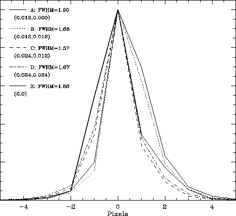
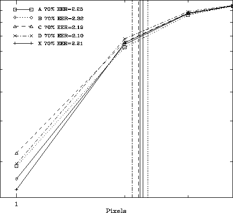
We investigate the effects of pixelization in the model by shifting
the detector in 12 µm steps in orthogonal directions. At each
step we used the same SAOSAC raytrace for test H-IAI-CR-1.001 and
plotted the cumulative radial distributions and one pixel slices in
y through the model and test spots as shown in Figures 19 and 20. The XRCF data in both plots is shown
as the thick solid line. The average 70% encircled energy radius and
full width for the four realizations of the model is
<EER(70%)> = 2.14 ± 0.08 pixels and
<FWHMy> = 1.74 ± 0.14 pixels.
By comparison, for the XRCF data we find <EER(70%)> = 2.21 and <FWHMy> = 1.88 .
The model spot is systematically sharper by 0.07 pixels or ~3% in EER(70%) and 0.14 pixels or ~7% in FWHM. Although the model again appears to be slightly sharper than the data, the XRCF data are within one standard deviation of the variations due to pixelation. Figure 8 shows a fairly substantial range in the Al-K FWHM (1.5-1.9 pixels) for measurements with modest pileup. Similarly, Figure 9 shows a range in EER(70%) of 2.3-2.4 pixels at Al-K. The sizes of these small variations are on the order of the sizes of pixel structures such as the channel stops and gates on the front side devices, which have lower quantum efficiencies than the active pixel areas. Depending on the location of the spot centroid within a pixel (the images were not dithered) these sub-pixel structures could alter the spot size. Our CCD model makes no attempt to model the gates and channel stops, nor does it handle charge spreading perfectly. We cannot yet determine the relative contributions of the mirror model and detector until the detector model is upgraded, although we note following this section that the model spot seems to be slightly smaller than the XRCF spot on all scales.
| Energy | Slope | |||
| XRCF data | MARX data | |||
| 70% | 90% | 70% | 90% | |
| 3.5 keV | 2.18 | 3.40 | 2.39 | 3.70 |
| 5.2 keV | 1.72 | 2.59 | 2.43 | 3.41 |
| 6.4 keV | 2.87 | 3.71 | 2.86 | 4.14 |