


Recent memos: Update on ACIS contaminant, Jan 8 2010
The Advanced CCD Imaging Spectrometer (ACIS) is an X-ray imager. X-ray photons hitting the camera are detected individually and their position, energy and arrival time recorded. This allows for high resolution (~1 arcsec) imaging, moderate resolution spectroscopy and timing studies. ACIS can also be used with the High Energy Transmission Grating (and less commonly the Low Energy Transmission Grating) for high resolution spectroscopy.
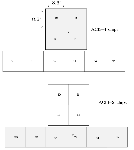
The Instrument layout is shown to the right. The back illuminated S3 chip offers the best spectral resolution without using a grating. For this reason, many observers choose the back illuminated S3 chip for high resolution imaging over small (few arcminutes) fields. The largest field of view is obtained by turning on the 4 ACIS-I front illuminated chips. This configuration is often used for surveys. The table below summarizes common instrument configurations, although others are available.
A complete description of ACIS is given in the Proposers' Observatory Guide.
| Common ACIS Configurations | |||||
|---|---|---|---|---|---|
| Scientific Use | CCDs | Aimpoint | FOV (arcmin) | Energy Resolution | Time Resolution |
| Wide Field Imaging | I0-I3 S2-S31 |
I3 | 16.9x16.9+ 16.9x8.3 |
130 eV (at 1.49 keV) 280 eV (at 5.9 keV) 2,3 |
3.2 s |
| High Resolution Imaging4 | S31 | S3 | 8.3x8.3 | 95 eV (at 1.49 keV) 150 eV (at 5.9 keV)2 |
3.2 s5 |
| Bright Source Fast Timing | S3 (CC-mode)6 | S3 (CC-mode) | 3x1024 pixels (1-D only)7 | 95 eV (at (1.49 keV) 150 eV (at 5.9 keV)2 |
2.85 ms |
| Bright Source High Resolution Spectroscopy8 | S0-S5 + HETG | S3 | 8.3x50.6 | Δλ 0.012-0.023 Å FWHM over 1.2-31 Å 0.1-10 keV |
3.2 s |
| Notes: 1. Other chips can also be selected. 2. Energy resolution measures at aimpoint. 3. Energy resolution depends on incident photon energy and position on the array. 4. The High Resolution Camera can also be used for imaging. 5. Time Resolution can be increased by using a sub-array at the expense of FOV. 6. In CC mode, or continuous clocking mode, data is continuously moved through the CCD and framestore yielding very high temporal resolution. 7. One spacial dimension is lost. 8. The Low Energy Transmission Grating can be used for spectroscopy in the 0.07-1.0 keV range. | |||||