During the winter and spring of 1996-1997, AXAF was calibrated at the X-Ray Calibration Facility (XRCF) at Marshall Space Flight Center in Huntsville, Alabama. The facility consists of a large vacuum tank connected via an evacuated pipe over 500 meters long to a set of X-ray sources. This allowed the optics (the High Resolution Mirror Assembly (HRMA)) to be placed in a nearly parallel X-ray beam, and to bring X rays with a known spectrum to a focus. Figure 5 summarizes the experimental setup at XRCF.
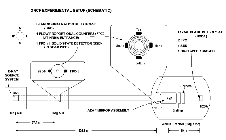
Figure 5: XRCF experimental setup (schematic).
An array of detectors was used during the calibration. The HRMA was calibrated with nearly identical detectors placed at the focal point of the telescope, near the HRMA entrance, and in the beam pipe close to the sources. The non-focal plane detectors were used to monitor the flux incident upon the HRMA. To first order, this allows detector effects to cancel out in the mirror calibration experiments.
The detectors included Flow Proportional Counters (FPC) (two at the focal plane, four at the HRMA entrance, and one some 38 meters from the X-ray source) and solid state detectors (SSD) (one in the focal plane and one 38 meters from the X-ray source in the beam pipe). The FPCs and SSD in the focal plane had a variety of selectible apertures. Finally, there was a high-speed imager (HSI), a microchannel plate camera. The entire focal plane assembly was able to be moved around in the vicinity of the telescope focus.
These detectors were used to measure, at a variety of X-ray energies, a number of properties of the HRMA. These include the effective area of the mirrors; the encircled energy curves for each of the four constituent mirror pairs in the HRMA, and of the HRMA ensemble; images of the point spread function; the faint wings of the point spread function; the shape of the focal surface; and images at the so-called ``ring focus''. The finite source distance at XRCF causes the converging rays to come to a sharp, ring-shaped focus near the infinite-source-distance focal length. It is thus possible to reconstruct the azimuthal position on the optics from which photons were reflected, to look for irregularities in the mirror construction (such as deformations at the 12 mounting points on each optic).
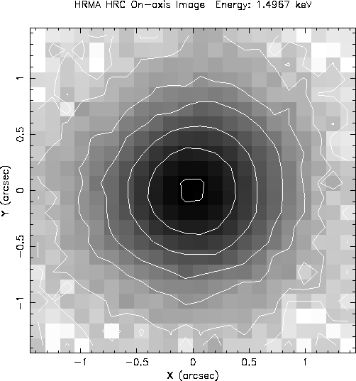
Figure 6: Simulated on-axis point sourceĀHRMA/HRC-I images
(without aspect blurring) at 1.49 keV. Contours are logarithmic and spaced
in factors of 3.ĀĀThe innermost contour is at 90% of the peak surface
brightness.
The mirror was tested on its side in a one-gravity environment, with the source at a finite distance. In actual use, of course, it will be operated in zero-g with sources at infinity. The point of the ground calibration, therefore, was in large part to validate a high-fidelity ray trace model suite which simulates every part of the telescope performance, both on the ground and on orbit. By establishing that the model can reproduce the calibration data to high accuracy, we build confidence that the model can also predict the on-orbit performance of the telescope.
In a word, the mirror looks very good. The on-axis point spread function is nicely peaked with full widths at half maximum in the sub-arcsecond range. In figure 6, we show a simulation of the on-orbit, on-axis point spread function at an energy of 1.49 keV, which is based on a detailed raytrace model, updated as a result of the HRMA calibration. The contour lines are logarithmic, spaced at factors of 3 in surface brightness. The highest contour is at 90% of the peak surface brightness. The simulation does not account for aspect determination blurring. The sub-arc-second performance can be easily seen. The effective area as a function of energy is within a few percent of expectations. A few mysteries remain to be elucidated, but on the whole the results are very satisfactory. Our simulations, in general, successfully reproduced the measurements, given the knowledge of the optics we had before the test. The added knowledge we gained about optic positions has been incorporated into our models.
During this time period (Phase 1; December 1996 through February 1997), in addition to the HRMA calibration, a large number of tests were carried out to calibrate the flight objective transmission gratings. The tests included effective area measurements, and determinations of spatial and spectral resolution.
Between mid-February and late April 1996 (Phase 2), the flight instruments (ACIS and HRC) were placed into the test facility, allowing testing of the AXAF telescope in close to flight configuration: mirror, gratings, and science instruments in a series of end-to-end tests with real X-rays. The beam normalization detectors (FPCs and SSD) used in Phase 2 were the same as those used in Phase 1. This allows easier application of mirror data from Phase 1 to the results of Phase 2 with the flight detectors.
During the calibration, we collected more than 690,000 spectra. The HRMA calibration alone involved 982 separate tests, over 293,000 pulse height spectra, and nearly 1500 HSI images. Full analysis is in progress!
Richard Edgar, Diab Jerius, T. J. Gaetz, and Ping Zhao