The AXAF launch is less than a year away! Currently, TRW and Kodak are integrating the telescope (including HRMA optic, LETG and HETG gratings, and optical bench); Ball is integrating the focal-plane instruments (HRC and ACIS) into the Science Instrument Module, before shipping it to TRW for AXAF integration. The major (and we mean MAJOR) science milestones this past year were delivery and system-level testing and calibration of the HRMA and all AXAF science instruments (LETG, HETG, HRC, and ACIS).
In this newsletter, we report on the calibration of the AXAF observatory at MSFC's X-Ray Calibration Facility (XRCF). First we describe the calibration program at the XRCF; next the X-ray calibration instrumentation; and finally a few key preliminary results.
The calibration program at the XRCF not only accumulated essential data, it also provided a system-level test of the flight AXAF observatory. During about a dozen at-vacuum phases, calibration at the XRCF instrument chamber occupied about 6 months of intense (around-the-clock) activity over a one-year period. Calibration of the AXAF observatory lasted about 4 months, with about 3 X-ray months of remarkably productive data collection.
In daily meetings led by Project Science, the Science team planned impending measurements in a detailed Calibration Measurements Data Base (CMDB), maintained by the AXAF Science Center (ASC). Based on the CMDB, the TRW Test Conductor prepared a test-list script for conducting the planned measurements. Despite a few failures in ground-support equipment, which were eventually rectified, daily (in some cases, real-time) replanning enabled useful data collection to continue with little loss in efficiency. The CMDB comprised 3200 measurements with the HRMA, which accumulated 4 million seconds of X-ray data, at an average efficiency of 50%.
Certainly, the dedication and cooperation of the entire AXAF calibration team contributed to this success. We sincerely thank the members of the contributing organizations: MSFC Systems Analysis & Integration Laboratory (SAIL); TRW Space & Electronics Group; Ball Aerospace & Technologies; Eastman Kodak Company (EKC); MSFC Project Science; SAO Telescope Science; SAO Mission Support Team (MST); AXAF Science Center (ASC); SAO HRC team; MIT and PSU ACIS team; SRON and MPE LETG team; and MIT HETG team.
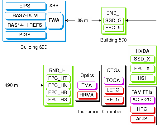
Figure 1: Configurations of X-ray sources, monitor detectors, X-ray optics,
transmission gratings, and focal-plane detectors during calibration
of the AXAF observatory at the MSFC X-ray Calibration Facility (XRCF).
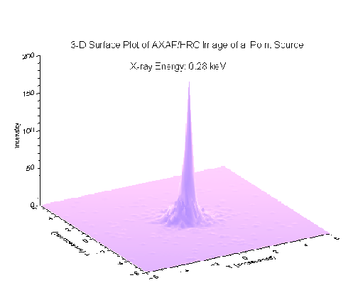
Figure 2: Surface plot of the HRMA-HRC-I point spread function (PSF) at
0.28 keV
(C-K ![]() ) shows that the full width at half maximum (FWHM) is about
0.5 arcsec. The expected on-orbit FWHM is about 0.3 arcsec.
Clearly, AXAF will provide unprecedented high-resolution imaging for
X-ray astronomy.
(Plot is from the SAO HRC team.)
) shows that the full width at half maximum (FWHM) is about
0.5 arcsec. The expected on-orbit FWHM is about 0.3 arcsec.
Clearly, AXAF will provide unprecedented high-resolution imaging for
X-ray astronomy.
(Plot is from the SAO HRC team.)
XRCF provided unique capabilities for calibrating the AXAF observatory. A 518-m guide tube separates the X-ray sources from the instrument chamber. With a useable volume of 18-m length by 6-m diameter, the instrument chamber provides a controlled thermal-vacuum environment large enough to accommodate any Space Shuttle Orbiter's payload.
Figure 1 illustrates AXAF calibration configurations at the XRCF. The X-ray Source System (XSS) comprises the Electron-Impact Point Source (EIPS), a rotating -anode source with a Double-Crystal Monochromator (RAS7 -DCM), a rotating-anode source with the (reflection-grating monochromator) HIgh-Resolution Erect-Field Spectrometer (RAS14-HIREF), the Penning Ionization Gas-discharge Source (PIGS), and the two-stage Filter-Wheel Assembly (FWA). The HRMA X-ray Detection System (HXDS) includes 6 Beam-Normalization Detectors (BNDs) -- 1 Solid-State Detector (SSD) and 5 Flow Proportional Counters (FPCs).
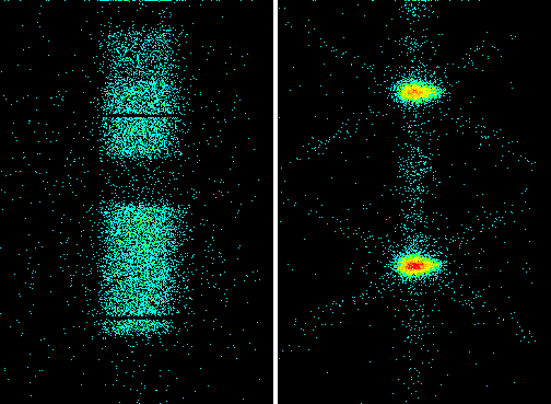
Figure 3: HRMA-LETG-HRC-S zoomed, dispersed image of Al-IV lines at 160.07 Å\
and 161.69 Å shows that the LETGS resolution is about 0.08 Å.
The left
panel is a dithered image; the right panel, a de-dithered image.
The dispersion direction is vertical in this figure.
The resolved elongation of the image results from the 2-arcsec length of
the Penning-source exit slit.
Clearly, AXAF will provide unprecedented high-resolution spectroscopy
for X-ray astronomy.
(Images are from the MPE LETG team.)
Prior to arrival of AXAF's High-Resolution Mirror Assembly (HRMA) at the XRCF, the rehearsal used the (non-flight) Technology Mirror Assembly (TMA), which had demonstrated AXAF mirror technology a decade earlier. Because AXAF's Low-Energy Transmission Grating (LETG) and High-Energy Transmission Grating (HETG) are incompatible with the TMA geometry, the rehearsal employed the (non-flight) TMA Objective Grating Assembly (TOGA), containing both LETG and HETG flight-like grating facets.
Prior to arrival of AXAF's (microchannel plate) High-Resolution Camera (HRC) and AXAF CCD Imaging Spectrometer (ACIS), the rehearsal and the HRMA calibration used 4 different focal-plane detectors. Three -- an SSD, an FPC, and the (microchannel plate) High-Speed Imager (HSI) -- are part of the HRMA X-ray Detector Assembly (HXDA). The fourth, the (non-flight) ACIS two-chip (ACIS-2C) served as a surrogate for the ACIS.
Detailed analysis of the calibration data is to be completed about 3 months prior to AXAF's launch. Owing to the massive body of data and the ambitious accuracy goals, the analysis will be every bit as challenging as the measurements. The objective of the analysis is to determine model parameters which best fit the entire body of data, modifying modeled physics where necessary to avoid ad hoc empirical adjustments. This approach not only gives a means of interpolating (in energy and position), but also provides a method for transferring ground-based measurements to an on-orbit calibrated observatory.
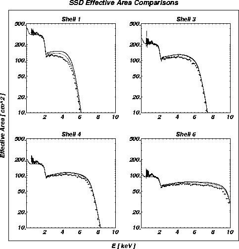
Figure 4: Comparison of measured and predicted effective area of each
HRMA shell shows
a discrepancy of about 10%.
The solid line denotes predicted effective area over the entire focal plane;
the dotted line, that within a 20-arcsec radius.
Data points are obtained by dividing the count rate of the focal-plane
SSD for a continuum source (EIPS with carbon target at 15 kV) by that of
the monitor SSD, and appropriately accounting for distance and aperture.
(Plots are from the MSFC Project Science team.)
We conclude with 3 sample results. The first 2 demonstrate AXAF's unprecedented capabilities for high-resolution imaging (Fig. 2) and for high-resolution spectroscopy (Fig. 3) The third indicates the remaining challenge to fit a physical model to the measured effective area, at an accuracy of about a few percent (Fig. 4).
Martin Weisskopf & Steve O'Dell