
|
| Figure 1:The HRC focal-plane layout |
The HRC-I orientation with respect to the spacecraft has a nominal "45 degree" rotation relative to the spacecraft axis, as shown in figure 1. This angle has not been well calibrated. The recent series of Capella observations that were performed for deriving improved HRC-I degapping corrections provide an ideal data set for determining the angle between the HRC-I crossed-grid charge detector (CGCD) axes and the Science Instrument Module (SIM) translation axis (spacecraft Z-axis). In this set of observations Capella was observed "on-axis" with a different SIM-Z offset used for each observation.
|
|
| Figure 1:The HRC focal-plane layout |
|
|
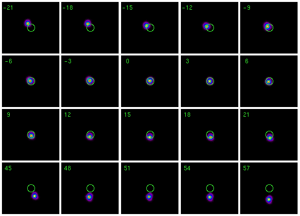
Figure 2: Images of the spot from Capella for the 20
observations (ObsIDs 654-6559 inclusive) performed during
2005 December and 2006 January. The SIM was at a different
translation offset for each of the observations; the
offset in mm is indicated in the upper left-hand corner of
each spot image. The circle in each image has a radius of
1 arcsec and is centered on the nominal position of
Capella given its J2000 coordinates and the observed
proper motion (RA = 05:16:41.4026,
Dec = +45:59:50.190).
The trend for spot to get progressively farther from the nominal location as the SIM translation gets larger can be explained by the failure of standard processing to correctly account for the rotation angle between the HRC-I crossed-grid charge detector and the SIM translation axis. |
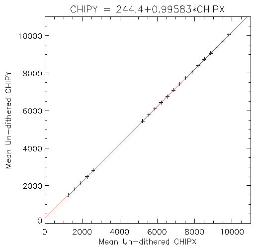
The rotation angle can be determined from where the nominal on-axis position is for each SIM translation offset given the observed event positions in CHIP coordinates. Unfortunately, the mean observed CHIP coordinates are not good for this purpose 1) because of the spacecraft dither and 2) because Capella was not observed directly on-axis. However both of these "offsets" can be removed using the known position of Capella and the aspect solution.
|
| Figure 3: Nominal on-axis CHIPY vs CHIPX for the 20 SIM translation offsets, over-plotted with the best-fit line. |
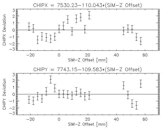
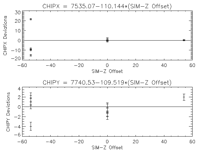
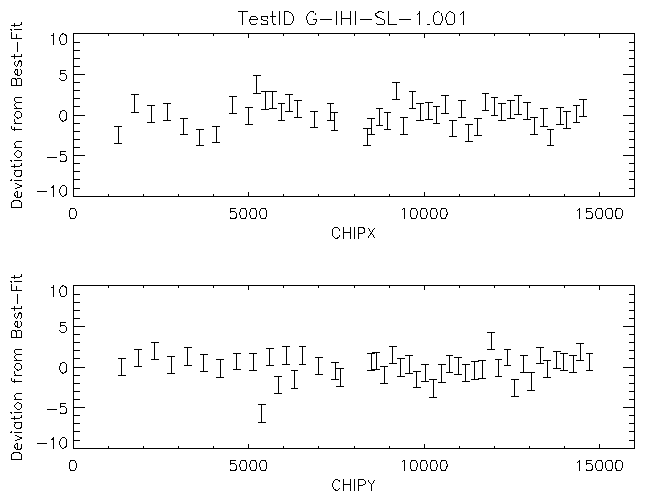
A similar result can be obtained using the independent fits of each of the CHIP axes to the SIM translation offset. Figure 4 shows the deviations of the CHIP coordinates from the best-fit line as a function SIM translation offsets. The best-fit lines are
| CHIPX = (7530.23 ± 0.14) + (-110.043 ± 0.005) × SIM-Z offset |
| CHIPY = (7743.15 ± 0.14) + (-109.583 ± 0.005) × SIM-Z offset |
The ratio of the slopes corresponds to a rotation angle of 44.880 ± 0.002. Combining the slopes also provides a measure of the HRC-I pixel size. The value of 6.4392 ± 0.0002 µm is somewhat larger than the value from subassembly measurements (6.4294 µm) and this discrepancy should be investigated further. It may be that the discrepancy can be attributed to the SIM translation calibration (i.e. the reported translation step size is ~0.15% too large). The fits also provide values for the nominal on-axis CHIP position for the nominal SIM translation position (7530.23, 7743.15).
|
| Figure 4: Nominal on-axis CHIPX (upper) and CHIPY (lower) deviations from the best-fit line vs SIM translation offset |
|
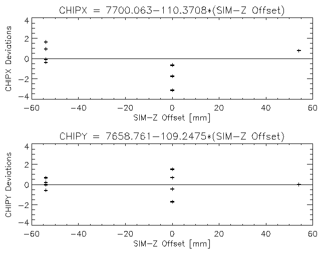
| Figure 5: Spot CHIPX (upper) and CHIPY (lower) deviations from the best-fit line as a function of SIM translation offset. |
|
| Figure 6: Nominal on-axis CHIPX (upper) and CHIPY (lower) deviations from the best-fit line vs SIM translation offset for the 1999-Sep-02 observations of HR 1099. All nine observations are included. |
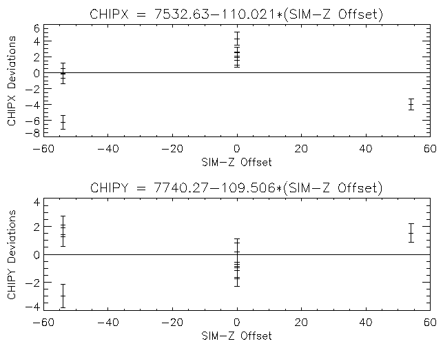
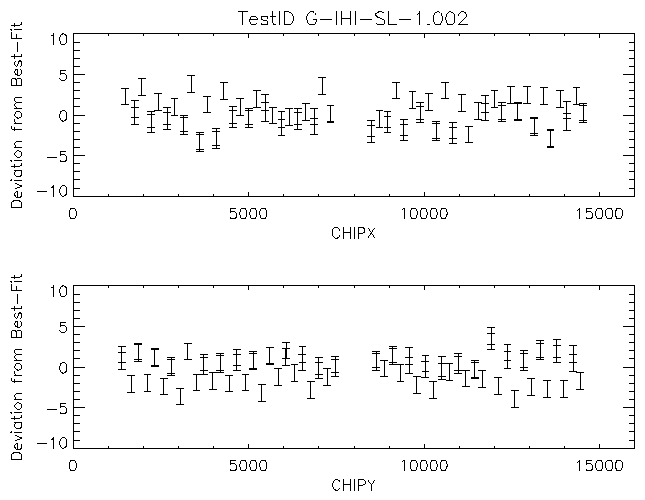
Figure 7 shows the result of re-fitting the data while ignoring the data from ObsID 1216. The fit is improved, although the chi-squared values are still large (CHIPX fit: 141.6, CHIPY fit: 41.5). The fit functions are:
| CHIPX = (7532.63 ± 0.26) + (-110.021 ± 0.007) × SIM- Z offset |
| CHIPY = (7740.27 ± 0.26) + (-109.506 ± 0.007) × SIM- Z offset |
These fits imply an HRC-I rotation angle of 44.865 ± 0.003, which is in closer agreement with the Capella results than with Ping's.
|
| Figure 7: Nominal on-axis CHIPX (upper) and CHIPY (lower) deviations from the best-fit line vs SIM translation offset for the 1999-Sep-02 observations of HR 1099. Data from ObsID 1216 are ignored in this fit. |
The difference in the analysis between the two methods is in accounting for the fact that the source is not observed on-axis and that the spacecraft roll, optical-bench "bending", and source off-axis position changes from observation to observation. Using the "raw" source spot positions does not account for these changes that we expect to have an impact on where the source appears in the detector.
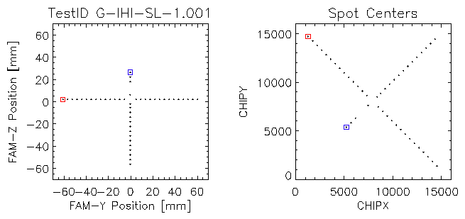
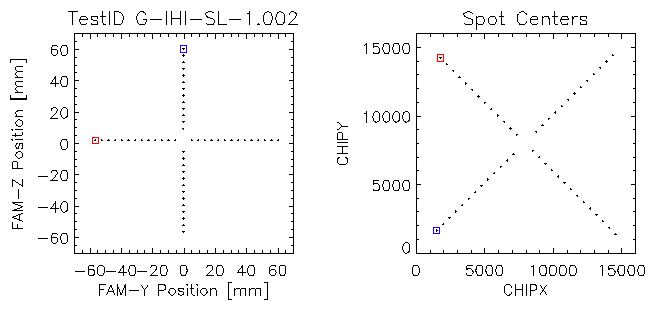
I have re-examined the data from that XRCF test, G-IHI-SL-1.001, as well as data from a second spatial-linearity test, G-IHI-SL-1.002, to derive alignments for both detector axes. The level 1 data is incomplete in the archive and had been processed with earlier versions of the CXCDS; so, I re-ran hrc_process_events on the level 0 event files. Correction for FAM motion was not applied in the processing. The FAM motion files were used to determine time intervals when the FAM was settled at one of the measurement points and for each interval the mean CHIP location of the source image was determined. The FAM pointings in the test sampled a large number of locations in the central ~10 mm by ~10 mm region of the HRC-I as well as points along each diagonal. In order to avoid a bias from over-weighting by the points in the center they were ignored in the analysis, as were points that has FAM X-axis (focus) positions off of the nominal value. The locations of the selected points from the two tests are shown in figure 8.
|
|
| Figure 8: Positions of the FAM and X-Ray spot images in CHIP coordinates for the selected pointings from TestIDs upper G-IHI-SL-1.001 and lower G-IHI-SL-1.002. Blue and red squares encircle the first and last points for orientation reference. |
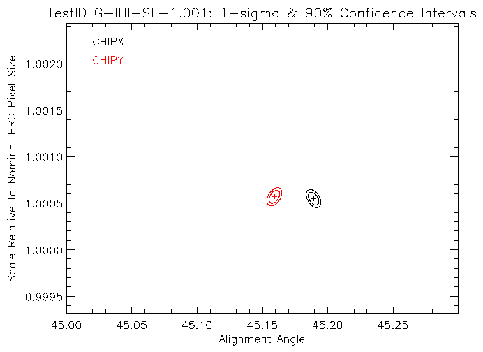
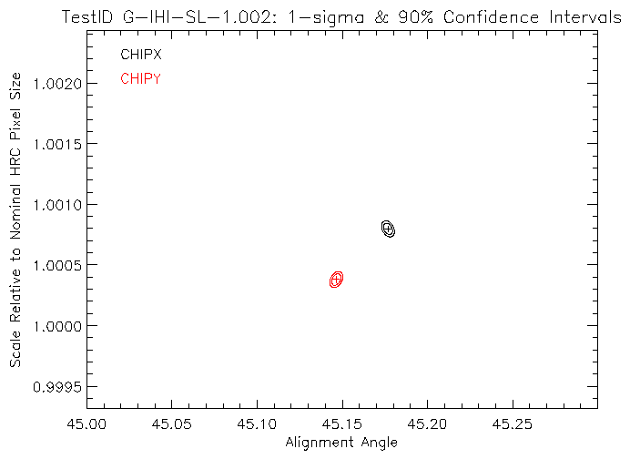
The alignment of each HRC-I axis relative to the FAM axes was performed independently. The FAM axes were assumed to be orthogonal and to have the same translation scale. The relations
|
|
|
|
| Results of fits of each of the HRC-I CHIP axes to the FAM axes for TestIDs left G-IHI-SL-1.001 and right G-IHI-SL-1.002. | |
The best-fit alignment angles and scales are in reasonable agreement between the two tests if we allow for the possibility that the sizes of the confidence intervals are underestimated. The rotation angles for the G-IHI-SL-1.001 are in good agreement with the earlier analysis. The average of the angles for two axes is 45.174 degrees, which once the details of how the WCS-Y location moves with the FAM Y-axis motion of the previous analysis is accounted for becomes 44.826 degrees. Similarly the average of the scales for the two axes is in good agreement with the previous analysis. Once again while the rotational alignment measurements cannot be directly applied to the mounting relative to the SIM translation axis, the rough agreement between the XRCF data and the on-orbit data is likely to indicate the relative alignment of the HRC-I axes to the HRC mounting points.
One additional result from these fits is that the two HRC-I axes appear to be ~0.03 degrees (~1.8 arcmin) off of orthogonal. One way to think of this is that the grooves used to wrap the wires of the CGCD are shifted along one edge of the detector by ~70 µm. The impact of this non-orthogonality is a position shift of ~7 pixels from one side of the HRC-I active area to the other; a small enough amount that it can be ignored.
Last modified: Wed Mar 23 13:07:55 EDT 2011
Dr. Michael Juda
Harvard-Smithsonian Center for Astrophysics
60 Garden Street, Mail Stop 70
Cambridge, MA 02138, USA
Ph.: (617) 495-7062
Fax: (617) 495-7356
E-mail: mjuda@cfa.harvard.edu