| Filter transmission vs. energy, ACIS-I - postscript | Filter transmission vs. energy, ACIS-S - postscript |
 Source data |
 Source data |
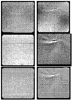
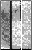
| The following two images were taken from the Figures 5.13 and 5.14 of the Science Instrument Calibration Report for ACIS, Version 1.81, September 30, 1998. | |
| (Click on images to see full-size versions) | |
|---|---|
 Imaging Array Filters 009(left) and 019 (right). The top images show the filter transmission at 273 eV (Filter 009: T~24.8%; Filter 019: T~27.8%); the middle images are 522 eV maps (Filter 009: T~50.5%; Filter 019: T~53.1%); the bottom images are 775 eV maps (Filter 009: T~75.3%; Filter 019: T~77.1%). The left filter (009) was chosen as the imaging array flight unit. It is quite uniform at all energies mapped, implying that both the polyimide substrate and the aluminum coatings have uniform thickness and will contribute minimally to artifacts in ACIS images. The 273 eV map of filter 019 shows smooth but substantial variation in the aluminum thickness, although some "pinwheel" striations due to spinning out the polyimide are detectable in this image as well as in the higher- energy maps. These complex curved features correlate well row-to-row within a given image and between images, confirming that they are not artifacts of the data collection. |
 Spectroscopy Array Filter 003, with the 273 eV map (T~34.9%) at the left, the 522 eV map (T~56.5%) in the middle, and the 775 eV map (T~79.0%) at the right. The smooth transmission gradient at low energies is presumably due to slight nonuniformities in the aluminum coatings. The diverging striations visible in the 522 and 775 eV maps are from the polyimide substrate. This is the most uniform of the polyimide-based spectroscopy array filters. |


