The calibration of AXAF's High Resolution Camera (HRC) proceeds in three primary stages: Sub-Assembly, X-ray Calibration Facility (XRCF), and On-Orbit Verification (OOV). Although the most interesting data- real astronomical sources, true flight configuration, and the lack of gravitational distortion of the mirrors- is not taken until OOV, interpreting this data depends critically upon the two other (earlier) stages. This is because due to the nature of the calibration observations- taken on orbit, monitoring sources whose intrinsic nature is poorly understood- we are not able to adequately control the experimental inputs.
Ideally most of the calibration would be performed in the XRCF stage where we will have a flight-like configuration and well characterized X-ray sources being focused by the mirrors almost as they will be after launch. The details of the calibration and XRCF facility have been outlined in an earlier issue of this newsletter(No. 3 Sept. 1995) by Dr. J. Juda. The most important constraint on the XRCF stage is time. While there are 60 days of continuous (24 hour) calibration time available, this must be shared between the four Science Instruments: the AXAF CCD Imaging Spectrometer (ACIS), HRC, and the High and Low Energy Transmission Gratings (HETG and LETG respectively). Further, the use of a focused beam, necessarily sampling a very small area, is particularly poorly suited to many of the required calibrations- particularly the large area ones such as gain mapping, and quantum efficiency.
The Sub-Assembly stage of the calibration begins with a component by component characterization and follows the entire buildup process. A flow chart/bubble diagram showing the major components of this process is given in Figure 5.
The first elements to be tested are the Micro-Channel Plates. The quantum efficiency (QE) and gain are measured as a function of energy, photon incident angle and plate bias voltage across the entire detector surfaces by illuminating them with a flat field. Measurement of the QE fine structure, and the durability of the plates (Gain Fatigue) are also measured. Since these last two measurements extract large amounts of charge from the plates- a process which degrades the performance of the detector- they are performed on flight-like detectors and not the actual flight Micro-Channel Plates.
The next primary elements to be tested are the UV Ion Shields. The spatial uniformity and transmission response as a function of energy are both measured on the flight UV Ion Shields. As with the Micro-Channel Plates some tests, such as UV/visible transmission and fine structure transmission in X-rays, are difficult to perform on the flight unit and instead witness samples from the production runs are used.
Then the Micro-Channel Plates and UV Ion Shields are combined and their convolved performance is tested against the predictions of our model. The QE and gain are again measured as a function of energy and incident photon angle across the entire detector. The energy resolution and scale- a characterization of the pulse height distribution- are also quantified. Last, the integrity of the UV Ion Shield is tested (UV/Visible response and Ion Beam Response tests).
Simultaneous to the calibration of the Micro-Channel Plates with their UV Ion Shields, the other elements of the instrument- the Flight Electronics, the Cross-Grid Charge Detector, and the Flight Calibration Source - are characterized. The Cross-Grid Charge Detector is the component that collects the charge clouds produced by the Micro-Channel Plates from X-ray photons, and the Flight Calibration Source will be used as a transfer standard to OOV as well as a performance monitor throughout the life of the instrument.
At this point, the emphasis shifts to characterizing the HRC's contribution to the imaging performance on-orbit and confirming that at each step of the build-up the instrument performs as predicted from the data taken previously. The various elements are combined into two full flight detector assemblies, one for imaging and one for spectroscopy (HRC-I and HRC-S respectively). Each of the flight detectors is run through a battery of confirming tests: background, dead time and count rate linearity, UV response, QE, gain, energy resolution and scale. Using masked X-ray illumination the spatial resolution, linearity and scale for each detector are quantified.
Although we expect our initial model and its predictions to be quite robust, allowances have been made for the exploration of unusual results that might occur at any stage in the build-up process. A recent finding was that the two layers of Aluminum coating, one on each side of the Lexan substrate of the UV Ion Shield, were behaving as a Fabry-Perot interferometer and allowing substantial UV light leaks. This discovery led to a design change of the UV Ion Shield that completely corrected the problem.
With all of these data in hand we are ready to test our model of the HRC's performance with the next stage of the build-up. The instrument will be assembled into a flight-like configuration and placed behind the flight mirror assembly at the XRCF. This stage of the calibration will finalize our numbers for many of the parameters of interest (QE, deadtime correction and count rate linearity) as well as exposing the detector to a converging focused beam for the first time. This stage will also produce our first significant results on the PSF.
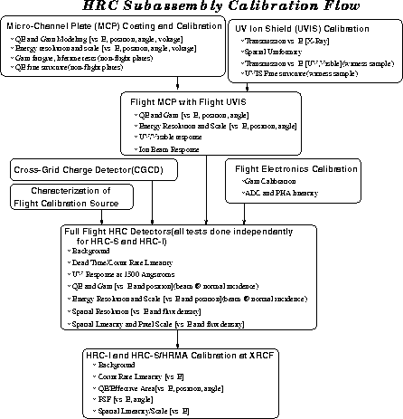
Figure 5: A flow chart of the steps in the HRC subassembly calibration.
This accumulation of data will allow us to minimize the number of variables when we arrive at the OOV stage. Thus we will be able to finalize the PSF model and the other remaining free parameters of the HRC with the least impact on the AXAF Guest Observer Program.
R. Hank Donnelly