During transmission measurements of a flight type HRC-I UV/Ion shield a high transmission was found for the 2537 Å line from a Hg lamp. Further measurements of the transmission featured resonance transmission peaks[1]. Subsequent modeling of the HRC-I UV/Ion shield design[2] showed that the high transmission could be understood as originating from Fabry-Perot interference effects caused by the Al/Lexan/Al sandwich construction of the UV/Ion shield. This discovery has lead to a redesign of the flight UV/Ion shields for both the HRC-I and HRC-S. The basic fix is to replace the Lexan of the original design with polyimide, a material that is more UV absorbing. Additionally for the HRC-I UV/Ion shield, the aluminum coating on the side close to the MCP is changed to carbon.
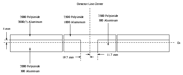
There are actually four UV/Ion Shields in the HRC, one for the imaging detector and three for the spectroscopy detector. Among these four there are three different material geometries and several thickness combinations. Figure 1 shows the physical layout of the new UV/Ion shield design with the currently planned material thicknesses labeled while table 1 lists the new baseline material thicknesses. The thick aluminum for the outer segments is designed to be used as a low energy suppression filter; it absorbs the expected first order diffracted x-rays with at least a factor of ten attenuation relative to the transmission in the thin aluminum region. A pair of spectra, one taken off the thick aluminum strip and one on, may be used to disentangle the higher order contributions to the source spectrum from first order. It is unclear a present whether the thick aluminum coating can actually be successfully fabricated; mechanical stresses at the edge of the thick coating may damage the polyimide membrane.

| Detector | Polyimide (Å) | Aluminum (Å) | Carbon (Å) |
| HRC-I | 5000 | 700 | 200 |
| HRC-S Inner ``T'' | 2500 | 1000 | 0 |
| HRC-S Inner | 2500 | 300 | 0 |
| HRC-S Outer | 2000 | 300 | 0 |
| HRC-S Outer ``Strip'' | 2000 | 2000 | 0 |
The x-ray transmission as a function of energy of one of the UV/Ion shields can be calculated given the elemental composition of its constituents, the density and thickness of each, and the atomic mass absorption cross sections. The polyimide formulation used for the HRC UV/Ion shields has a chemical stoichiometry C14H6N2O4 and a density of 1.4 g cm-3. Bulk aluminum and carbon have densities of 2.7 g cm-3 and 2.2 g cm-3 respectively. The ``as deposited'' aluminum density is closer to 2.5 g cm-3. Atomic mass absorption cross sections have been tabulated[3] and are accessible through the saolib routine rdacon and the script atcon. I have written a program to produce transmission curves of aluminum and carbon coated films of Lexan and/or polyimide. The executable can be found in:
/data/juda1/juda/asc/hrc/code/uvis/new_uvis_x_trans.
This routine asks whether to include a material (Lexan, polyimide, aluminum, aluminum oxide, and carbon) and prompts for thicknesses in angstroms.
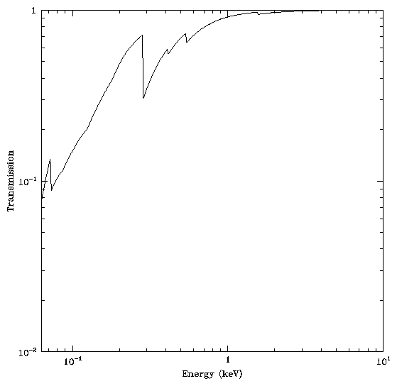
Figure 2 is the x-ray transmission as a function of energy for the new design of the HRC-I UV/Ion shield.
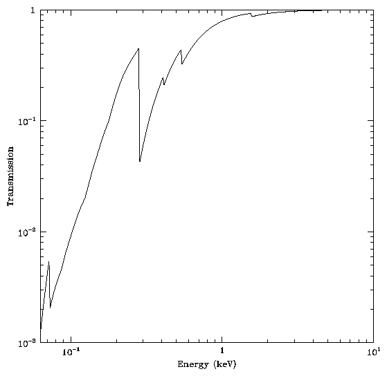
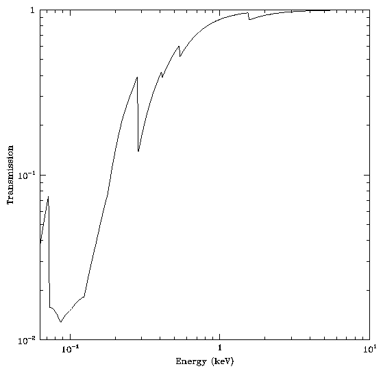
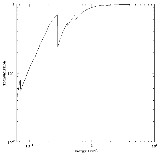
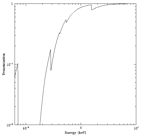
Figures 3-6 are similar to figure 2 but for the UV/Ion Shields over the inner and outer segments of the HRC-S in areas with both the thin and thick aluminum coating. ASCII text files containing these calculated transmissions can be found in the directory
| HRC-I | uvis_x_polyimide5000_al700_c200 |
| HRC-S Inner ``T'' | uvis_x_polyimide2500_al1000 |
| HRC-S Inner | uvis_x_polyimide2500_al300 |
| HRC-S Outer | uvis_x_polyimide2000_al300 |
| HRC-S Outer ``Strip'' | uvis_x_polyimide2000_al2000 |
In practice the actual thicknesses for each of the materials will be determined by comparison of transmission measurements taken at several energies to model calculations such as these.
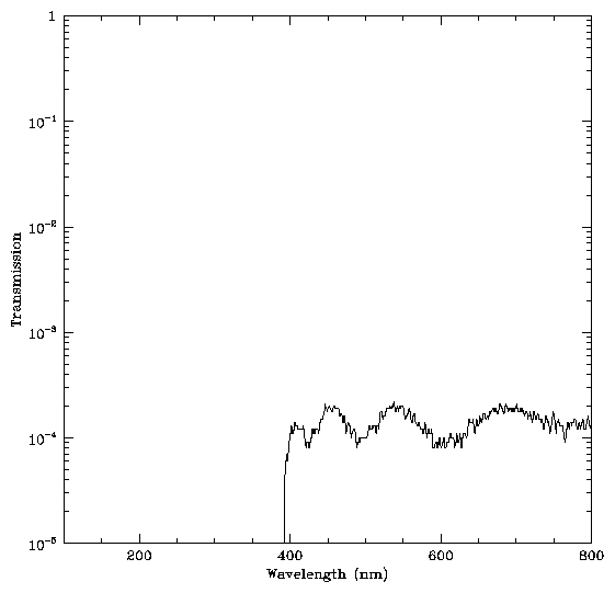
The UV transmission of the UV/Ion shield can be calculated by modeling it as a multi-layered interference filter[2]. The complex indices of refraction as a function of wavelength of the constituent materials must be input to the model. Unfortunately, the index of refraction as a function of wavelength for polyimide are not well known in the UV. In order to asses the performance of the new HRC-I design, a sample filter was made by the UV/Ion shield vendor. The actual material thicknesses of the sample were 5555 Å polyimide with 705 Å of aluminum on one side and 218 Å of carbon on the opposite side. Figure 7 is a plot of the measured transmission of the sample as a function of wavelength.
Dr. Michael Juda
Harvard-Smithsonian Center for Astrophysics
60 Garden Street, Mail Stop 70
Cambridge, MA 02138, USA
Ph.: (617) 495-7062
Fax: (617) 495-7356
E-mail: mjuda@cfa.harvard.edu