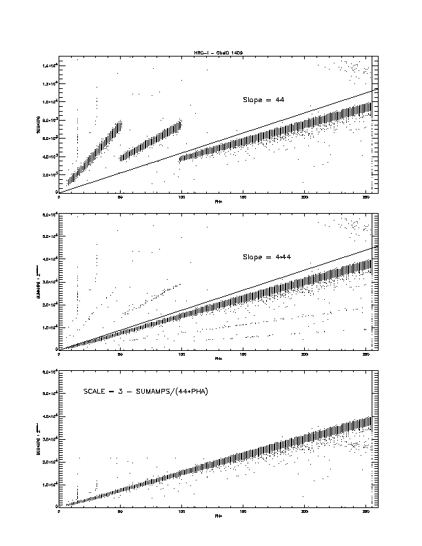
Figure 1 Un-scaled and scaled SUMAMPS versus PHA for HRC-I events
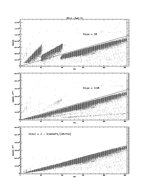
As described above, the amplifier gains are adjusted according to the size of the MCP trigger. We do not have a direct measure of the size of the MCP trigger; however, we expect it to be related to the event PHA, which is a measure of the total charge collected on the CGCD. Figure 1 shows scatter plots of event SUMAMPS (without and with scaling) as a function of event PHA taken from on-orbit HRC-I data. The un-scaled SUMAMPS versus PHA is shown in the top panel; the breaks in the band of points indicate a change in the amplifier gain. The central panel shows the result of scaling according to the reported AMP_SF value; while most of the events lie along the expected band there are additional bands at 2× and 4× as well as at 1/2× and 1/4× the nominal scaled SUMAMPS to PHA ratio. The bottom panel shows the result of scaling using a scale factor calculated from the SUMAMPS and PHA that I describe below. Figure 2 is similar for on-orbit data from the HRC-S.

Figure 1 Un-scaled and scaled SUMAMPS versus PHA for HRC-I events

Figure 2 Un-scaled and scaled SUMAMPS versus PHA for HRC-S events
Since the events in SUMAMPS versus PHA space break into well defined regions, it is suggestive that we work "backward" from these to determine what the actual scale was. Plotted in the top panels of figures 1 and 2 are lines of constant SUMAMPS/PHA that separate the AMP_SF = 3 region from the others. For the HRC-I this ratio is around 44 while for the HRC-S the value for the ratio is around 38. A scheme for determining the correct scale as used in the bottom plots in figures 1 and 2 is given by the following pseudo-code:
# PHA is the event pulse height
# SUMAMPS is the sum of the 6 CGCD taps (i.e. AU1+AU2+AU3 + AV1+AV2+AV3)
# RATIO is a fixed test value passed in as a parameter
#     (e.g. for HRC-I, RATIO = 44; for HRC-S, RATIO = 38)
# SCALE is the "corrected" amplifier scale factor

if ( PHA == 0 )
   SCALE = 1
else if ( PHA >= 255 )
   SCALE = 3
else
   SCALE = 3 - (int)(SUMAMPS / (RATIO * PHA))
   if ( SCALE < 1 ) SCALE = 1
endif
This corrected scale factor would be compared to the AMP_SF value and if not equal a bit in the event STATUS word would be set to indicate that a correction was required. All event calculations that had used AMP_SF would use SCALE instead.