

Creating ACIS RMFs with mkacisrmf
Analysing Data
Instructions on how to run this tool are given in the mkacisrmf analysis thread.
The tool mkacisrmf is used to create RMFs for:
- all -120 ACIS data taken in (V)FAINT mode that has the time-dependent gain adjustment and CTI correction applied
- -120 ACIS GRADED mode data on the back-illuminated chips (ACIS-S1 and S3) only that has the time-dependent gain adjustment applied
- -110 ACIS data taken on the back-illuminated chips (ACIS-S1 and S3) only that has the time-dependent gain adjustment applied
All new analyses with these types of data should be done with mkacisrmf instead of mkrmf. The results from mkacisrmf and mkrmf are very similar, except for the following cases:
-
The new RMFs are 10-15% more accurate at energies lower than 1 keV.
-
Calibration for the ACIS-S1 (ccd_id=5) back-illuminated chip has been greatly improved.
Scripts: specextract and psextract
There are specific cases when mkacisrmf may be used in conjunction with the specextract or psextract scripts to create more accurate RMF files. Refer to the appropriate section of the mkacisrmf thread for more information:
Figure 1 and Figure 2 also illustrate when to use mkrmf versus mkacisrmf.
Using Consistent Calibration
The calibration applied to the event file must be consistent with the RMF tool chosen or a systematic energy shift will occur.
- -120 C Data: mkacisrmf
-
For data taken at the -120 C focal plane temperature, the newest gain file is automatically selected when acis_process_events is run. The CTI and TGAIN corrections must also be applied when reprocessing the data. There is TGAIN calibration for GRADED mode data, but no CTI correction.
acisD2000-01-29gain_ctiN0006.fits
Note that any file since version 4 (gain_ctiN0004) is "good enough" for use with mkacisrmf.
- -120 C Data: mkrmf
-
If you wish to finish an analysis using mkrmf, you must process the data with the version 2 gain file (acisD2000-01-29gain_ctiN0002.fits). Set the gainfile parameter to:
unix% pset acis_process_events \ gainfile=$CALDB/data/chandra/acis/bcf/gain/acisD2000-01-29gain_ctiN0002.fits - -110 C Data
-
For data taken at the -110 C focal plane temperature on the back-illuminated chips (ACIS-S1 and S3), the appropriate gain file is automatically selected when acis_process_events is run. The TGAIN correction must also be applied when reprocessing the data; there is no CTI available for -110 C.
acisD1999-09-16gainN0006.fits
Analysis for the -110 C front-illuminated chips must still be done with mkrmf.
Technical Details
The mkacisrmf tool contains all the functionality of the previous tool mkrmf. Unlike its predecessor, however, mkacisrmf separates the RMF calculation process into two components: an "ideal" component which describes the CCD spectral response prior to the effects of CTI, and a spatially varying component which incorporates the changes in the response produced by CTI.
This new method was motivated primarily by a desire to provide a more rapid means of developing ACIS response calibration products. Accompanying the new tool is a new CCD analysis reference data (ARD) file which describes both the ideal response and the spatial variation produced by CTI. In contrast to traditional CCD FEFs, the CTI-induced spatial variations can be generated directly from numerical simulations of the CCD response obviating the need for laborious fitting at each position on the CCD. This human-intensive fitting was the primary bottleneck in generating ACIS FEFs. Once the "scatter matrix", describing the spatial variations, has been generated automatically, small scale adjustments are included to account for differences between the simulated response and the actual CCD response as measured using data from the onboard calibration source.
The algorithm contained in mkacisrmf is based upon the the algorithm in Alexey Vikhlinin's tool calcrmf2, which is described in his memo "Updates to the RMF model in the ACIS FI CCDs" (PDF). The CIAO tool is essentially a direct translation of this prototype code and includes a number of enhancements including an improved interpolation scheme to calculate the response at intermediate energies between the available calibration points. All functionality of the previous tool mkrmf is available including the ability to produce weighted response matrices for arbitrary spatial regions.
Figures
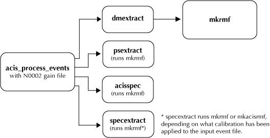
Figure 1. Using mkrmf in an analysis thread.
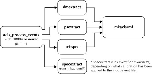
Figure 2. Using mkacisrmf in an analysis thread.