Characteristics of the HRC
Background
Michael
Juda
Outline
of Talk
-
- HRC Background Reduction
Measures
-
- Background Components
-
- Temporal Behavior
-
- HRC-I Spatial Distribution
-
- HRC-S Spatial Distribution
-
- Future Directions
For more details see "Characteristics of
the On-Orbit Background of the Chandra X-ray Observatory High
Resolution Camera", 2002, SPIE Proc.
4851
HRC Background Reduction
Measures
HRC MCPs made from ``low-noise''
glass
The HRC detector housing is surround on five sides by plastic
scintillator for use as an active anti-coincidence
shield.
-
- Signals from shield are used
to flag MCP events caused by penetrating
particles
-
- Flagging works for the HRC-I
but not for the
HRC-S
For each MCP event, telemetry contains info on the shape of the
charge distribution from the MCP as well as state of on-board
hardware checks. Particle event signature is different from x-ray
event. (see poster by C.
Wilton)
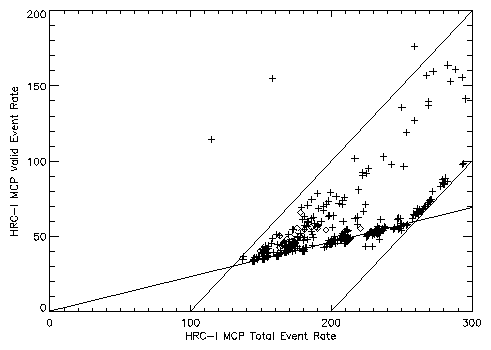
HRC telemetry also contains scalars to report rates: MCP triggers
(Total rate), triggers that pass on-board validity checks (Valid
rate), and antico-shield
rate.
Background
Components
-
- Internal ( ~ 10
counts/s)
-
- radioactive isotopes within instrument
materials
-
- detector
noise
-
- External ( ~ 150 - a few
×1000
counts/s)
-
- cosmic
rays
-
- solar
flares
-
- coronal mass ejections
(CMEs)
-
- Earth's trapped radiation
belts
CXO particle detector (EPHIN) measures the local radiation
envirnoment.
-
electrons
- four energy channels in the range 0.25-10
MeV
-
protons
- four energy channels in the range 5.0-53
MeV
- Integral
channel
- electrons with E > 8.7 MeV, protons and nuclei with E >
53
MeV/nucleon
Temporal
Behavior
Variation in the background observed since mission
start.
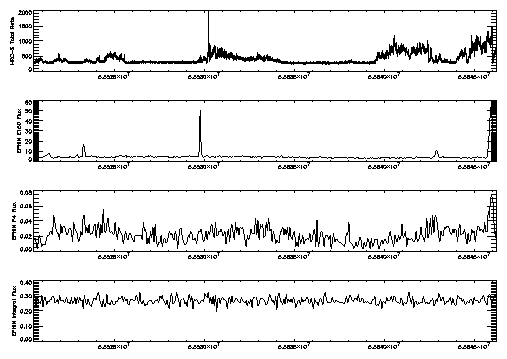
Flaring on time scales of seconds to hours observed on top of a
quiescent
level.
Reasons for
variability:
-
- solar flares and
CMEs
-
- transit of fringes of
radiation
belts
-
- solar-cycle modulation of
cosmic ray
flux
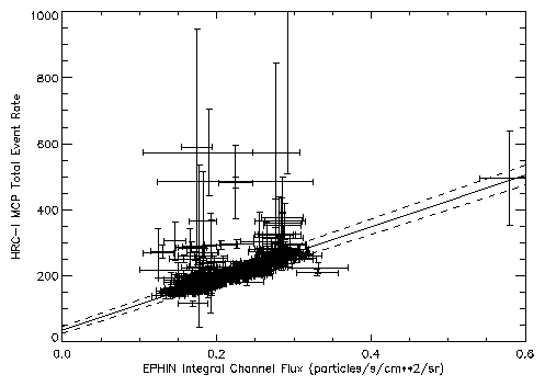
HRC-I MCP trigger rate correlates with the EPHIN high-energy
particle flux (ignoring X-rays and the flaring
component)
Flaring Background
HRC-I Spatial
Distribution
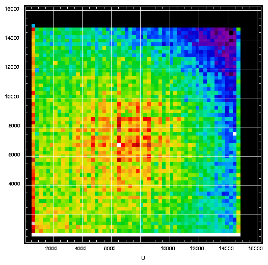
Reasons for spatial
variation
-
-
``Hot-spots''
-
- detector gain/sensitivity
variations
-
- antico-shield sensitivity
variations
-
- shielding by surrounding
materials
| Non-Sky-Viewing
Background |
 |
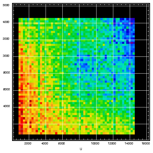 |
| Raw |
Filtered |
| Combined AR Lac
Fields Background |
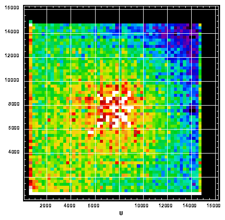 |
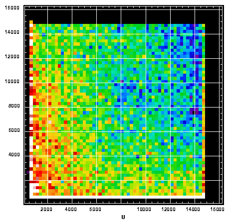 |
| Raw |
Filtered |
Coincidence shield flagged
Events
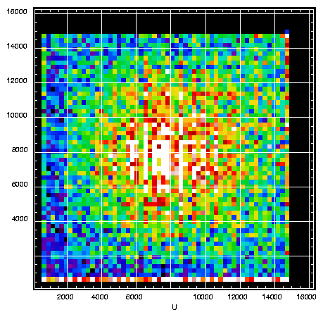
HRC-S Spatial
Distribution
Reasons for spatial
variation
-
-
``Hot-spots''
-
- detector
gain/sensitivity variations, including UV/ion
shield
-
- shielding by
surrounding
materials
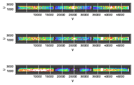
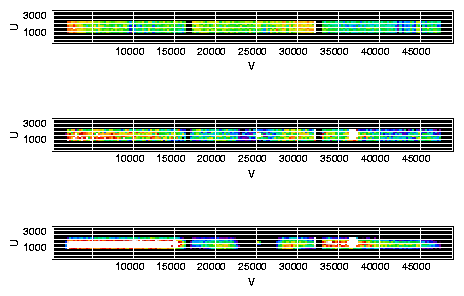
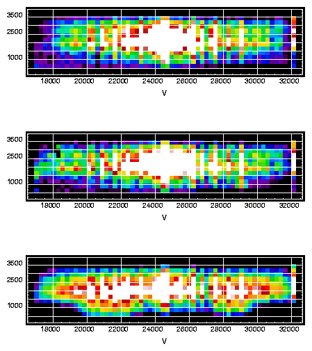
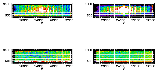
HRC-S is operated in several different modes depending on the type
of observation. Modes select different areas of the
detector.
HRC-S Spectroscopy Mode (Default)
HRC-S Spectroscopy Mode (Default) - Filtered
| HRC-S ``Timing''
Mode |
 |
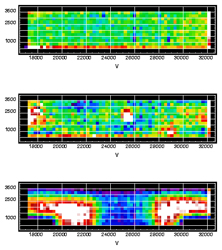 |
| Raw |
Filtered |
HRC-S Edge-Blank Center vs ``Timing'' Mode
Future
Directions
-
- Track temporal
changes
-
- Continue to refine
characterization
-
- Changes in the ``quiescent'' distribution over
the
solar-cycle
-
- Are there differences in flaring correlated
with:
-
- Rate in flaring
component
-
- Characteristics observed in EPHIN or particle
detectors on other
spacecraft
-
- Time since recent solar flare or
CME
-
- Proximity to the Earth's radiation
belts
-
- Develop models for estimating the background
for a given
observation
File translated from TEX
by TTH, version 3.01.
On 22 Nov 2002, 11:55.
Tags
2002 : background : CfA : Chandra : CXC : HRC : HRC background : HRC-I : HRC-S : Juda
[add a tag to this presentation]
Last modified: Fri Nov 22 12:43:48 EST 2002
Dr. Michael Juda
Harvard-Smithsonian Center for Astrophysics
60 Garden Street, Mail Stop 70
Cambridge, MA 02138, USA
Ph.: (617) 495-7062
Fax: (617) 495-7356
E-mail: mjuda (at) cfa.harvard.edu
